Topcon Controller
364
0
0
Pełen tekst
(2)
(3) P O S I T I O N I N G. S Y S T E M S. TopSURV Reference Manual. Part Number 7040-0025 Rev. E. ©Copyright Topcon Positioning Systems, Inc. December, 2004 All contents in this manual are copyrighted by Topcon Positioning Systems, Inc. All rights reserved. The information contained herein may not be used, accessed, copied, stored, displayed, sold, modified, published, or distributed, or otherwise reproduced without the expressed written consent from Topcon Positioning Systems, Inc..
(4) ECO#2373.
(5) TOC. Table of Contents Preface .................................................................. ix Terms and Conditions ...................................................... ix Manual Conventions ........................................................ xiii. What’s New with TopSURV ................................. xv Chapter 1. Introduction .......................................................... 1-1 Title Bar ........................................................................... 1-2 Menu Bar ......................................................................... 1-2 Security ............................................................................ 1-3 Chapter 2. Job ......................................................................... 2-1 Open ................................................................................. Open Job .................................................................... New .................................................................................. New Job ..................................................................... Select Survey Configurations .................................... Coordinate System .................................................... Projections ................................................................. Grid to/from Ground Params .................................... Geoid ......................................................................... Add Geoid ........................................................... Units .......................................................................... Display ...................................................................... Alarms ....................................................................... Delete ............................................................................... Config .............................................................................. Config: Survey ................................................................. Select Survey Configurations ..................................... P/N 7010-0492. 2-2 2-2 2-3 2-3 2-4 2-5 2-6 2-7 2-8 2-8 2-9 2-11 2-12 2-12 2-13 2-14 2-14. i.
(6) Table of Contents. GPS+ Configuration .................................................. Configurations ..................................................... Config: Survey .................................................... Config: Base (Static) Receiver ............................ Config: Base Radio ............................................. Internal Hiper Lite ............................................... Pacific Crest Radio Parameters ........................... Satel Radio Parameters ....................................... Base Cell Phone Parameters ................................ Base Multicast Parameters .................................. Config: Base (Static) Antenna ............................ Config: Rover Receiver ....................................... Laser Config ........................................................ Config: Rover Radio ........................................... Config: Beacon .................................................... Config: WAAS .................................................... CDGPS Radio ..................................................... Config: EGNOS .................................................. Config: OmniSTAR ............................................ Config: Rover Antenna ....................................... Config: Init (Occupation) Times ......................... Config: Survey Parms ......................................... Config: Stakeout Parms ....................................... Config: Advanced ............................................... Total Station Configuration ....................................... Configurations ..................................................... Config: Survey .................................................... Config: Instrument .............................................. Config: Connection Mode ................................... Config: Cable ...................................................... Config: Radio ...................................................... Satel Radio Parameters ....................................... Config: Mode ...................................................... Config: Search/Track .......................................... Config: Survey Parameters ................................. Config: Stakeout Parms ....................................... Config: Miscellaneous ........................................ Config: Coordinate System ............................................... ii. 2-14 2-14 2-15 2-19 2-21 2-22 2-23 2-24 2-24 2-25 2-26 2-27 2-30 2-30 2-32 2-33 2-34 2-34 2-35 2-36 2-37 2-38 2-40 2-42 2-43 2-43 2-44 2-44 2-46 2-47 2-48 2-48 2-49 2-51 2-52 2-55 2-56 2-57. TopSURV Reference Manual.
(7) Table of Contents. Config: Units ................................................................... Config: Temperature/Pressure ......................................... Display ............................................................................. Alarms .............................................................................. Menu Display ................................................................... Config Menus ............................................................ Activate Modules ...................................................... Import .............................................................................. Import From Job ........................................................ Select Job ............................................................ Import From Job ................................................. Select Point Type(s) to Import ............................ Points to Import .................................................. Code .................................................................... Select Road(s) to Import ..................................... Select Point List(s) to Import .............................. Import Status ....................................................... Duplicate Objects ............................................... Import From File ....................................................... From File ............................................................ Import From Format ........................................... Text File Format ................................................. Custom Style ....................................................... Coordinate System .............................................. Import From LandXML ...................................... Select Data For Import ....................................... Import From Controller ............................................. Import/Export Settings ....................................... File Import Directory .......................................... Export .............................................................................. Export to Job ............................................................. Select Job ............................................................ Export To Job ..................................................... Select Point Type(s) to Export ............................ Points to Export .................................................. Code .................................................................... Select Road(s) to Export ..................................... Select Point List(s) to Export ............................... P/N 7010-0492. 2-57 2-58 2-58 2-58 2-59 2-59 2-60 2-61 2-61 2-61 2-63 2-64 2-65 2-66 2-66 2-67 2-68 2-68 2-69 2-69 2-71 2-72 2-73 2-73 2-74 2-75 2-76 2-76 2-77 2-78 2-78 2-78 2-79 2-80 2-81 2-82 2-82 2-83. iii.
(8) Table of Contents. Export Status ....................................................... Duplicate Objects ................................................ Export to File ............................................................. To File ................................................................. Select Point Type(s) to Export ............................ Points to Export ................................................... Select TN3 ........................................................... Export To Format ................................................ Text File Format .................................................. Custom Style ....................................................... Export to Controller ................................................... Import/Export Settings ........................................ Files To Export .................................................... Sessions ...................................................................... Info ................................................................................... Job Info ...................................................................... Mode ................................................................................. Observation Mode ...................................................... 2-84 2-84 2-85 2-85 2-87 2-87 2-88 2-88 2-89 2-90 2-90 2-90 2-91 2-92 2-93 2-93 2-94 2-94. Chapter 3. Edit ........................................................................ 3-1 Points ................................................................................ Display ....................................................................... Find by Point .............................................................. Find by Code .............................................................. Add (Edit) Point ......................................................... Code-Attributes .......................................................... Codes and Attributes ........................................................ Codes - Attributes ...................................................... Code ........................................................................... Attributes ................................................................... Point Lists ......................................................................... List of Point Lists ....................................................... Add/Edit Point List .................................................... X-Sect Templates ............................................................. Roads ................................................................................ Start Point ................................................................... iv. 3-2 3-3 3-4 3-5 3-5 3-7 3-8 3-8 3-9 3-9 3-11 3-11 3-12 3-14 3-17 3-19. TopSURV Reference Manual.
(9) Table of Contents. Horizontal Alignment ................................................ Line ..................................................................... Curve .................................................................. Spiral ................................................................... Intersection Point ................................................ Vertical Alignment .................................................... Vertical Grade ..................................................... Parabola .............................................................. Long Section ....................................................... X-Section ................................................................... Properties ................................................................... Calculate Road Points ............................................... Raw Data ......................................................................... Edit Raw Data ........................................................... Sessions ............................................................................ Session Setup ............................................................. 3-20 3-21 3-22 3-23 3-24 3-25 3-26 3-27 3-28 3-29 3-30 3-31 3-34 3-36 3-37 3-38. Chapter 4. View ....................................................................... 4-1 Enable .............................................................................. Zoom In/Out/Window ..................................................... Zoom All .......................................................................... Zoom To Point ................................................................. Toolbar ............................................................................. Properties .......................................................................... 4-2 4-2 4-2 4-2 4-3 4-4. Chapter 5. GPS Survey ........................................................... 5-1 Status ................................................................................ Elevation Mask .......................................................... Start Base ......................................................................... Multi Base ................................................................. Init mmGPS+ ................................................................... Transmitter ................................................................ Resection ................................................................... Known Point .............................................................. Add Point .................................................................. Calibration .................................................................. P/N 7010-0492. 5-2 5-4 5-8 5-10 5-10 5-12 5-14 5-15 5-18 5-18. v.
(10) Table of Contents. Topo ................................................................................. Line ............................................................................ Azimuth-Distance-Height .......................................... Laser BS Meas ........................................................... Config Laser ........................................................ Config Laser .............................................................. Auto Topo Survey ............................................................ Known Point Init .............................................................. X-Section .......................................................................... Find Station ...................................................................... Tape Dimension ............................................................... Static Occupation ............................................................. Localization ...................................................................... Add Localization Point .............................................. Localization Results .................................................... 5-20 5-29 5-30 5-32 5-32 5-33 5-34 5-38 5-39 5-39 5-39 5-40 5-41 5-43 5-44. Chapter 6. Total Station Survey ............................................ 6-1 Occupations and Backsight Survey Setup ........................ Backsight Survey ....................................................... Resection .................................................................... Elevation .................................................................... Multi-Point Backsight ................................................ Check Backsight ........................................................ Observations ..................................................................... Sideshot - Direct ........................................................ PTL Mode .................................................................. Offsets ........................................................................ Horizontal Angle Offset ...................................... Horizontal/Vertical Angle ................................... Distance Offset .................................................... Hidden Point ........................................................ Two Line Intersection ......................................... Line and Corner ................................................... Line and Offset .................................................... Plane and Corner ................................................. Cross-Section ................................................................... Find Station ....................................................................... vi. 6-2 6-2 6-5 6-8 6-10 6-12 6-13 6-14 6-16 6-18 6-19 6-22 6-23 6-24 6-25 6-26 6-27 6-28 6-29 6-31. TopSURV Reference Manual.
(11) Table of Contents. Tape Dimension ............................................................... Missing Line .................................................................... Auto Topo ........................................................................ Scanning .......................................................................... Remote Control ................................................................ Remote Control ......................................................... Rotate ......................................................................... 6-33 6-35 6-36 6-39 6-40 6-40 6-42. Chapter 7. Stake ...................................................................... 7-1 Points ............................................................................... Stakeout Point ........................................................... GPS+ Stakeout .......................................................... Configure Radio ................................................. TS Stakeout ............................................................... Configure Link ................................................... Point in Direction ............................................................. Point in Direction ...................................................... GPS+ Stakeout .......................................................... TS Stakeout ............................................................... Point List .......................................................................... Stakeout Point List .................................................... Stakeout (GPS and TS) ............................................. Select Point ......................................................... Lines ................................................................................ Stakeout Line ............................................................ GPS+ Stakeout .................................................... TS Stakeout ......................................................... Offsets .............................................................................. Line & Offset ............................................................ Stakeout Line & Offset ....................................... Station & Offsets ................................................ Initial Point Name ............................................... GPS+ Stakeout .................................................... TS Stakeout ......................................................... Intersection & Offsets ............................................... Intersection & Offsets ......................................... GPS+ Stakeout ..................................................... P/N 7010-0492. 7-2 7-2 7-4 7-5 7-6 7-7 7-8 7-8 7-10 7-10 7-11 7-11 7-13 7-13 7-14 7-14 7-15 7-16 7-17 7-17 7-17 7-19 7-20 7-21 7-22 7-23 7-23 7-25. vii.
(12) Table of Contents. TS Stakeout ......................................................... Curve & Offsets ......................................................... Curve & Offsets .................................................. Spiral & Offset ........................................................... Stakeout Spiral & Offset ..................................... Roads ................................................................................ Stakeout Road ............................................................ Initial Point Name ............................................... GPS+ Stakeout .................................................... TS Stakeout ......................................................... Stakeout Slope ........................................................... Stakeout Alignment ............................................. GPS+ Stakeout .................................................... TS Stakeout ......................................................... Stakeout Real Time Road .......................................... Initial Point Name ............................................... GPS+ Stakeout .................................................... TS Stakeout ......................................................... DTM ................................................................................. CodeStrings ....................................................................... 7-25 7-26 7-26 7-27 7-27 7-28 7-28 7-31 7-31 7-32 7-33 7-34 7-35 7-36 7-37 7-39 7-39 7-40 7-40 7-41. Chapter 8. COGO .................................................................... 8-1 Inverse .............................................................................. Inverse Point to Points List .............................................. Intersection ....................................................................... Inverse Point to Line ........................................................ Point in Direction ............................................................. Traverse ............................................................................ BS Point ..................................................................... Curve Solutions ................................................................ Curve Solution ........................................................... PI & Tangents ............................................................ Three Pt Curve ........................................................... Radius & Points ......................................................... Area ................................................................................... viii. 8-2 8-5 8-7 8-9 8-11 8-13 8-14 8-15 8-15 8-18 8-20 8-22 8-24. TopSURV Reference Manual.
(13) Table of Contents. Known Area ..................................................................... Hinge ......................................................................... Known Area - Hinge ........................................... Line ........................................................................... Known Area - Line ............................................. Transformations ............................................................... Rotate ........................................................................ Translate .................................................................... Scale .......................................................................... Select Points by Range ............................................... 8-26 8-26 8-26 8-29 8-29 8-31 8-31 8-32 8-33 8-34. Appendix A. File Formats .......................................................... A-1 Point Coordinate Formats ................................................ FC-4 ........................................................................... FC-5 ........................................................................... GTS-6 ........................................................................ FC-6/GTS-7 ............................................................... GTS-7 with strings .................................................... GT ............................................................................. DXF ........................................................................... SHP ........................................................................... Land XML ................................................................. CR5 ........................................................................... MOSS GENIO .......................................................... NEZ ........................................................................... NEZ with strings ....................................................... Cut Sheet Standard .................................................... Cut Sheet User Defined ............................................. Check Sheet ............................................................... PTL Sheet .................................................................. Code Libraries ................................................................. Topcon Data Dictionary (TDD) Format ................... XML Format ............................................................. Data Base Format (DBF) .......................................... Roads Formats ................................................................. SSS Road ................................................................... TDS Road ................................................................... P/N 7010-0492. A-1 A-1 A-2 A-2 A-3 A-3 A-4 A-4 A-4 A-4 A-5 A-6 A-7 A-7 A-8 A-8 A-9 A-10 A-10 A-10 A-11 A-12 A-13 A-13 A-14. ix.
(14) Table of Contents. MC Road .................................................................... LandXML Road ......................................................... TopSURV Road ......................................................... X-sect Templates Formats ................................................ SSS Template ............................................................. TDS X-section Template ........................................... TopSurv Template ..................................................... Localization Format ......................................................... GC3 ............................................................................ Roads Survey Formats ..................................................... X-Section Surveys ..................................................... Find Station Report .................................................... Raw Data Formats ............................................................ FC-5 ........................................................................... GTS-6 ........................................................................ FC-6/GTS-7 ............................................................... Land XML ................................................................. TDS RawData ............................................................ MOSS Survey ............................................................. A-17 A-18 A-18 A-20 A-20 A-20 A-21 A-22 A-22 A-22 A-22 A-22 A-23 A-23 A-23 A-24 A-27 A-27 A-28. Index. x. TopSURV Reference Manual.
(15) Preface. Preface Thank you for purchasing your Topcon receiver, survey product or accessory (the “Product”). The materials available in this manual (the “Manual”) have been prepared by Topcon Positioning Systems, Inc. (“TPS”) for owners of Topcon products. This Manual is designed to assist owners with the use of software (the “Software”) to be used with the Product and its use is subject to these terms and conditions (the “Terms and Conditions”). NOTICE. NOTICE. Please read these Terms and Conditions carefully.. Terms and Conditions PROFESSIONAL USE – Topcon Products are designed to be used by a professional. The user is required to be a professional surveyor or have a good knowledge of surveying, in order to understand the user and safety instructions before operating, inspecting or adjusting. Always wear required safety attire (safety shoes, hard hat, etc.) when operating the Products. COPYRIGHT – All information contained in this Manual is the intellectual property of, and copyrighted material of TPS. All rights are reserved. You may not use, access, copy, store, display, create derivative works of, sell, modify, publish, distribute, or allow any third party access to, any graphics, content, information or data in this Manual without TPS’ express written consent and may only use such information for the care and operation of your Product. The information and data in this Manual are a valuable asset of TPS and are developed by the expenditure of considerable work, time and. P/N 7010-0492. ix.
(16) Preface. money, and are the result of original selection, coordination and arrangement by TPS. TRADEMARKS – Topcon®, HiPer®, TopSURV™, Topcon Link™, Topcon Tools™, and Topcon Positioning Systems™ are trademarks or registered trademarks of TPS. Windows® is a registered trademark of Microsoft Corporation. Bluetooth® is a registered trademark owned by Bluetooth SIG, Inc. and is used by Topcon Positioning Systems, Inc. under license. Sokkia Corporation and the names of Sokkia Corporation products referenced herein are either trademarks or registered trademarks of Sokkia Corporation. Satel is a trademark of Satel, Oy. Other product and company names mentioned herein may be trademarks of their respective owners. DISCLAIMER OF WARRANTY – EXCEPT FOR ANY WARRANTIES IN AN APPENDIX OR A WARRANTY CARD ACCOMPANYING THE PRODUCT, THIS MANUAL, THE PRODUCT, AND ANY ACCOMPANYING SOFTWARE ARE PROVIDED “AS-IS.” THERE ARE NO OTHER WARRANTIES. TPS DISCLAIMS ANY IMPLIED WARRANTY OF MERCHANTABILITY OR FITNESS FOR ANY PARTICULAR USE OR PURPOSE. TPS AND ITS DISTRIBUTORS SHALL NOT BE LIABLE FOR TECHNICAL OR EDITORIAL ERRORS OR OMISSIONS CONTAINED HEREIN; NOR FOR INCIDENTAL OR CONSEQUENTIAL DAMAGES RESULTING FROM THE FURNISHING, PERFORMANCE OR USE OF THIS MATERIAL, THE SOFTWARE, OR THE PRODUCT. SUCH DISCLAIMED DAMAGES INCLUDE, BUT ARE NOT LIMITED TO, LOSS OF TIME, LOSS OR DESTRUCTION OF DATA, LOSS OF PROFIT, SAVINGS OR REVENUE, OR LOSS OF THE PRODUCT’S USE. IN ADDITION, TPS IS NOT RESPONSIBLE OR LIABLE FOR DAMAGES OR COSTS INCURRED IN CONNECTION WITH OBTAINING SUBSTITUTE PRODUCTS OR SOFTWARE, CLAIMS BY OTHERS, INCONVENIENCE, OR ANY OTHER COSTS. IN ANY EVENT, TPS SHALL HAVE NO LIABILITY FOR DAMAGES OR OTHERWISE TO YOU OR ANY OTHER. x. TopSURV Reference Manual.
(17) Terms and Conditions. PERSON OR ENTITY IN EXCESS OF THE PURCHASE PRICE FOR THE PORDUCT. LICENSE AGREEMENT – Use of the Software and any other computer programs or software supplied by TPS or downloaded from a TPS website (the “Software”) to be used with a Topcon Product constitutes acceptance of these Terms and Conditions in this Manual and an agreement to abide by these Terms and Conditions. The user is granted a personal, non-exclusive, non-transferable license to use such Software under the terms stated herein and in any case only with a single Product or single computer. You may make one (1) backup copy of the Software. Otherwise, the Software may not be copied or reproduced. You may not assign or transfer the Software or this license without the express written consent of TPS. This license is effective until terminated. You may terminate the license at any time by destroying the Software and Manual. TPS may terminate the license if you fail to comply with any of the Terms or Conditions. You agree to destroy the Software and manual upon termination of your use of the Product. All ownership, copyright and other intellectual property rights in and to the Software belong to TPS. If these license terms are not acceptable, return any unused Software and the Manual. CONFIDENTIALITY – This Manual, its contents and the Software (collectively, the “Confidential Information”) are the confidential and proprietary information of TPS. You agree to treat TPS’ Confidential Information with a degree of care no less stringent than the degree of care you would use in safeguarding your own most valuable trade secrets. Nothing in this paragraph shall restrict you from disclosing Confidential Information to your employees as may be necessary or appropriate to operate or care for the Product. Such employees must also keep the Confidentiality Information confidential. In the event you become legally compelled to disclose any of the Confidential Information, you shall give TPS immediate notice so that it may seek a protective order or other appropriate remedy.. P/N 7010-0492. xi.
(18) Preface. WEBSITE; OTHER STATEMENTS – No statement contained at the TPS website (or any other website) or in any other advertisements or TPS literature or made by an employee or independent contractor of TPS modifies these Terms and Conditions (including the Software License Agreement, Disclaimer of Warranty and limitation of liability). SAFETY – Improper use of a Topcon Product can lead to injury to persons or property and/or malfunction of the Product. The Product should only be repaired by authorized TPS warranty service centers. Users should review and heed the safety warnings in the manual accompanying the Product. MISCELLANEOUS – The above Terms and Conditions may be amended, modified, superseded, or canceled, at any time by TPS. The above Terms and Conditions will be governed by, and construed in accordance with, the laws of the State of California, without reference to conflict of laws.. xii. TopSURV Reference Manual.
(19) Manual Conventions. Manual Conventions This manual uses the following conventions: Example Explanation File Exit Enter Notes Topo. TIP. Click the File menu and click Exit. Indicates the button or key labeled Enter. Indicates a field on a dialog box or screen, or a tab within a dialog box or screen. Indicates the name of a dialog box or screen.. TIP. Supplementary information that can help you configure, maintain, or set up a system. NOTICE. NOTICE. Supplementary information that can have an affect on system operation, system performance, measurements, personal safety.. P/N 7010-0492. xiii.
(20) Preface. Notes:. xiv. TopSURV Reference Manual.
(21) What’s New. What’s New with TopSURV This chapter briefly describes new features and functions for version 4.11 of TopSURV. RTK and PP An additional mode for surveying and data collection. For details on configuring for RTK&PP survey type, see “Config: Survey” on page 2-15.. mmGPS+ RTK RTK survey mode using mmGPS+ system. For details on setup of mmGPS+ system, see “Init mmGPS+” on page 5-10.. Third Party TS support Now Sokkia/Leica total station models are supported. For details on formats, see “Config: Instrument” on page 2-44.. P/N 7010-0492. xv.
(22) What’s New with TopSURV. Multiport This is now supported for Base and Rover Receivers. For details on configuring with these modems, see “Config: Survey” on page 2-44.. Point Name + Constant and Station & Offset Staked out points can have these new parameters. For details on using them in point name design, see “Config: Stakeout Parms” on page 2-40.. Staked out Points Listed Staked out points are now listed along with the regular points. For details on editing points, see “Points” on page 3-2.. Linework Points collected with codes and strings can be joined with lines. For details on linework representation, see “Codes - Attributes” on page 3-8 and “Properties” on page 4-4.. xvi. TopSURV Reference Manual.
(23) What’s New with TopSURV. LandXML Import to TN3 DWG/DXF 3D-faces Import to TN3 Import Parcels from LandXML These Import/Export functions are now available. For details on import files, see “Import From File” on page 2-69.. Scatter plots for GPS RTK data RTK data can now be represented in graphic mode. For details on scatter plots, see page 5-4.. Storing codes for Base This is now available when starting the base station. For details, see “Start Base” on page 5-8.. Base Station Offsets These offsets can be added to correct the Base coordinates according to the offsets between the topo point’s known and observed coordinates, and then to recompute all points. For details, see page 5-26.. P/N 7010-0492. xvii.
(24) What’s New with TopSURV. DTM and Realtime Road Stakeout These have been added to the stakeout types available in TopSURV. For details on staking, see “DTM” on page 7-40 and “Stakeout Real Time Road” on page 7-37.. xviii. TopSURV Reference Manual.
(25) Chapter 1. Introduction TopSURV is Topcon’s survey software available for hand-held controllers. When installed on a hand-held controller that runs the Windows® CE operating system, such as Topcon’s FC-1000, FC-100 and FC-2000, TopSURV is used for: • field data collection • stakeout and control work The TopSURV main screen consists of a title bar, menu bar and a work area.. Figure 1-1. Main Screen. NOTICE. NOTICE. The appearance of the screen titles and text depend upon the device used. Most of the screen shots in this manual are obtained from an FC-1000.. P/N 7010-0492. 1-1.
(26) Introduction. Title Bar When on the main screen, the title bar displays the instrument button and the name of the job open (and the configuration name), the Reconnect button, as well as connection and controller power status icons. Controller Power Status. Job Name (Configuration Name). Instrument. Reconnect. Connection Status. Figure 1-2. Title Bar – Main Screen. If the controller has Bluetooth® wireless technology, the Reconnect button appears to reflect the status of Bluetooth connection. When within a menu option, the title bar displays the bitmap button, the name of the screen, and any system buttons required for various operations. Bitmap. Name of Screen. System Buttons. Figure 1-3. Title Bar – Menu Functions. Menu Bar The menu bar has seven menus used to configure and manage a survey job, and to control data.. Figure 1-4. Menu Bar. See the following chapters for a description of each menu and its functions.. 1-2. TopSURV Reference Manual.
(27) Security. Security Upon initial startup, a Security screen displays. TopSURV requires an access code to start. Contact a Topcon representative to acquire the necessary codes. • Key Value 1 and Key Value 2: the device’s numbers; record to give to a Topcon representative • Activation IDs: the fields in which to enter the security codes received from a Topcon representative to activate the purchased modes: TS, Robotic, GPS+, GIS (RT DGPS and PP DGPS), Roads, and mmGPS.. Figure 1-5. Security. P/N 7010-0492. 1-3.
(28) Introduction. Notes:. 1-4. TopSURV Reference Manual.
(29) Chapter 2. Job The Job menu includes the following menu items: • Open • New • Delete • Config • Import • Export • Info • Mode • Exit. Figure 2-1. Job Menu. P/N 7010-0492. 2-1.
(30) Job. Open To open a job, click Job Open.. Open Job The Open Job screen can be used to select a job.. Figure 2-2. Open Job. The Job List field contains the names of all existing jobs created/ opened using this software. When a job is selected in this list, the Created and Modified fields will reflect when the job was created and last modified. • Browse: displays the open job screen to browse directories for selecting the job to open. • Open: makes the chosen job current. Initially the Job List is empty. The following screen is opened when selecting the Browse button. Highlight the file to open and press OK. The selected job will now be opened and program will return to the main screen (Figure 2-3 on page 2-3).. 2-2. TopSURV Reference Manual.
(31) New. Figure 2-3. Open Job. New To open a new job, click Job. New.. New Job The New Job creation process is performed with the help of a Wizard. Press the Next button after all the fields of this screen have been set. The information will be saved after the Finish button is pressed and the selected values will be stored. The new job becomes current and takes all the settings from the previously open job, unless changed.. Figure 2-4. New Job. •. : displays the directory where the job will be created. Press Browse to change the directory.. P/N 7010-0492. 2-3.
(32) Job. • Name: the name of the new job. • Created By: the name or some other identifier of the surveyor. • Comments: any additional information about the project, for example, the conditions of survey. • Current Date: displays the current date. • Browse: changes of the job directory. • Next: opens the Select Survey Config screen. • Finish: saves the settings and returns to the main screen.. Select Survey Configurations Survey Configuration is a set of parameters that does not depend on the job. One Configuration can be used by several Jobs.. Figure 2-5. Select Survey Config. The description of how to work with configurations (edit existing and create new) will be discussed in “Config” on page 2-13. Initially, TopSURV contains pre-defined configurations: My RTK, My RTK and PP, My Network RTK, My mmGPS+ RTK, My RT DGPS, My PP Static, My PP Kinematic and My PP DGPS for the GPS+ mode; and My Conventional, My Reflectorless, and My Robotic for the Total Station mode. • GPS+ Config (for the GPS+ mode): shows the GPS+ Configuration for the current job. The drop-down list shows the configurations available for the GPS+ mode. To edit the configuration press the 2-4. button. TopSURV Reference Manual.
(33) New. • TS Config (for the TS mode): shows the total station Configuration for the current job. The drop-down list shows the configurations available for the TS mode. To edit the configuration press the. button.. • Enable Job History: when this box is checked, every surveyor’s operation on the job will be entered and saved in the file. • Back: returns to the previous screen. • Next: opens the Coordinate Systems screen. • Finish: saves the settings, creates a new job, and returns to the main screen.. Coordinate System This screen contains coordinate system information for the new job.. Figure 2-6. Coordinate System. • Projection: specifies the projection to be used. The button opens the Projections screen where active projections can be manipulated (added from a list of pre-defined projections, deleted). • Use Grid to Ground: when this box is checked, the button becomes available to open the Grid to/from Ground Param screen where transformation parameters are set to place grid coordinates to a near ground reference surface and vice versa.. P/N 7010-0492. 2-5.
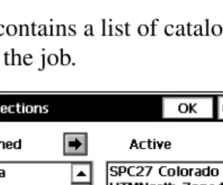
(34) Job. • Datum: shows the datum for the selected projection. The dropdown list displays all datums pre-defined in the current version: WGS84, NAD83, ETRS89, ITRF. The unavailable.. button is. • Geoid Model: shows the geoid selected (if any). The button opens the Geoids List screen where geoids can be added, deleted, or their properties viewed. • Back: returns to the previous screen. • Next: opens the Units screen.. Projections The Projections screen contains a list of cataloged projections, that can be chosen for use in the job.. Figure 2-7. Projections. • Pre-Defined: contains the tree of available projections divided by regions. • Active: contains the list of chosen projections (corresponds to the drop-down list in the Projections field of the Coordinate System screen). The first time the screen is opened, it is empty. •. : selects the chosen projection in the Pre-Defined panel and inserts it into the Active panel.. •. : deletes the highlighted projection from the Active panel.. 2-6. TopSURV Reference Manual.
(35) New. • OK: saves the changes and returns to the Coordinate System screen.. Grid to/from Ground Params The Grid to/from Ground Params screen is used to convert point coordinates from the grid projection to another reference surface to produce near ground values of distances. After the work is complete, the point coordinates can be converted back to the grid projection. The Grid to/from Ground Params screen contains the parameters of the Grid to Ground and Ground to Grid coordinate transformation.. Figure 2-8. Grid to/from Ground Params. TIP. TIP. The “hand” symbol means the function is selectable. Press the button to display the parameter and enter a value. • Scale Factor/Avg Job Ht: sets the value of the corresponding parameter: scale or average job height. • Direction: selects coordinate transformation type, either from Grid to Ground or from Ground to Grid • Az Rotation: the angle value in degrees. • Offsets: sets the offsets of the origin along the North and East axes to reduce coordinates to manageable values. • OK: returns to the Coordinate System screen.. P/N 7010-0492. 2-7.
(36) Job. Geoid Geoid is a physical reference surface. Its shape reflects the distribution of mass inside the earth. Geoid undulations are important for converting GPS-derived ellipsoidal height differences to orthometric height differences. The Geoids List screen contains a list of Geoids available for selection from models previously downloaded to the controller.. Figure 2-9. Add Geoid. • Add: opens the Add Geoid screen. • Remove: deletes the geoid from the list. • Edit: opens the Add Geoid screen to change the geoid.. Add Geoid From the Add Geoid screen, select a Geoid file from the controller and see the boundaries of the geoid application.. Figure 2-10. Geoid Parameters. 2-8. TopSURV Reference Manual.
(37) New. After being chosen, the geoid file appears in the Geoids List screen. The job will refer to the selected geoid file when performing calculations. • Geoid Format: the format of the geoid; either Geoid 99, Australian, Canadian 2000, Canadian 95, Geoid 2003, Mexico 97, or GeoidGFF. • Browse: opens the Select Geoid screen for choosing the geoid file from the disk. After the geoid is chosen, the fields in the lower part of the screen display the coordinates of the north-west and south-east points of the geoid. • Geoid Boundary: sets the boundary of the geoid application. : the longitude and latitude of the point that sets the north-west boundary of the geoid. : the longitude and latitude of the point that sets the south-east boundary of the geoid.. Units The Units screen displays the default units that will be used in the job.. Figure 2-11. Units. • Distance Units: units of linear measurements for the job. These can be Meters; IFeet - (International Feet, 1 Ifoot = 0.3048 Meters); US Feet (1 USFt = 1200/3937 Meters); IFeet and Inches, or US Feet and Inches (the latter two are calculated taking into account that 1 Foot = 12 Inches). P/N 7010-0492. 2-9.
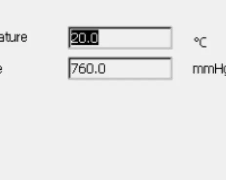
(38) Job. TIP. TIP. If the selected units are USfeet, linear values can be entered as meters, or IFeet by appending “m” or “if” to the entered value. If the selected units are in meters, then a linear value in USFeet, or International feet can be entered by appending “f”, or “if” to the end of the entered value. If the selected units are in IFeet, linear values can be entered in meters or USfeet by appending “m”, or “f” to the entered value. The appended characters “m”, “f”, or “if” are case insensitive. In other words, enter “M”, “F”, or “IF”. • Angle Units: units of angular measurements for the job. These can be Degrees, Grads (Gons), Radians (for Cogo use only), or Mils (for Cogo use only). (360 degrees = 400 grads = 2 π radians = 6400 mils.). TIP. TIP. Azimuth and distances can be entered as two points separated by “-”, “,” or “;”. Certain angles can be entered as three points separated by “-”, “,” or “;”. For instance a value of 100-101 indicates the Azimuth or Distance from Point 100 to Point 101. • Temperature (only for TS mode): units of temperature, used only for the raw measurements. These can be Celsius (C), or Fahrenheit (F). • Pressure (only for TS mode): units of atmosphere pressure, used only for the raw measurements. These can be mmHg, or hPa. • Back: returns to the previous screen. • Next: opens the Display screen. • Finish: saves the settings and returns to the main screen.. 2-10. TopSURV Reference Manual.
(39) New. Display The Display screen customizes the software interface.. Figure 2-12. Display. • Coord Type: displays the coordinate type for the projection selected. • Coord Order: the Northing/Easting order and height type of the local coordinates. • Azimuth Origin: the reference direction of azimuth. • Disp Dir As: select whether to display the direction as bearing or azimuth. • Disp CL Pos As: select how to display the position on the center line: as station or chainage. • Back: returns to the previous screen. • Next: opens the Alarms screen. • Finish: saves the settings and returns to the main screen.. P/N 7010-0492. 2-11.
(40) Job. Alarms The Alarms screen sets the sound alerts for situations of low power, low memory, poor radio link, and loss of initialization for the controller, GPS+ receiver (GPS+ column), or total station (TS column). Place check marks to select the desired alert conditions.. Figure 2-13. Alarms. • Audible Alarm: check this field to enable audible alarms. The alert will sound automatically when an alert situation occurs. • Back: returns to the previous screen. • Finish: saves the settings and returns to the main screen.. Delete To delete a job, click Job. Delete.. Figure 2-14. Delete Job. 2-12. TopSURV Reference Manual.
(41) Config. The Delete Job screen deletes jobs. Once deleted from the Job List, the file containing the job chosen is deleted from the disk. By default, the job files are stored in the \Jobs folder in the directory where the application has been installed. • Browse: If a job is not listed in this list, browse through the directories to select the job for deletion. • Delete: deletes the job. • Close: closes the screen without deleting job.. Config The Config submenu changes the parameters set during Job creation.. Figure 2-15. Config Submenu. P/N 7010-0492. 2-13.
(42) Job. Config: Survey To configure a survey, click Job. Config. Survey.. Select Survey Configurations The Select Survey Configurations screen can also be reached using the New Job Wizard (see “New” on page 2-3). (Note, that the appearance of the screen depends upon the mode enabled).. Figure 2-16. Select Survey Config. •. : opens the Configurations screen that edits the parameters of the configurations.. • Enable Job History: when this box is checked, every surveyor’s operation on the job will be entered and saved in the file. • Finish: sets the selected configuration for the current job and returns to the main screen.. GPS+ Configuration To configure a GPS+ survey, press the button in the GPS+ Config field of the Select Survey Config screen.. Configurations The Configurations screen presents a list of available configurations (Figure 2-17 on page 2-15). Editing and adding of a configuration is accomplished with the help of a Wizard.. 2-14. TopSURV Reference Manual.
(43) Config: Survey. Figure 2-17. Configurations. • Delete: deletes the highlighted configuration. • Edit: opens the Config: Survey screen for changing configuration settings. • Add: opens the Config: Survey screen for adding a new configuration. • OK: returns to the Select Survey Configurations screen.. Config: Survey The Config: Survey screen contains general settings for the configuration.. Figure 2-18. Config: Survey. • Name: the name of the configuration that will be displayed in the Configurations screen.. P/N 7010-0492. 2-15.
(44) Job. • Type: the type of the configuration; either RTK, RTK and PP, Network RTK, My mmGPS+ RTK, My mmGPS+ Network RTK, Real Time DGPS, PP Static, PP Kinematic, or PP DGPS. “PP” means Post-Processing. – RTK (Real Time Kinematic) implies, first, a pair of receivers operating simultaneously and, second, a radio link established between the two receivers. From a functional point of view, the two receivers will differ from each other. One of the receivers (usually referred to as the Base Receiver) is located at a fixed point with known coordinates. The base receiver will transmit the differential corrections to the other receiver (usually referred to as the Rover Receiver) via a radio link. To establish a proper connection between the two receivers, specify necessary communication parameters first. – RTK and PP (Real Time Kinematic and Post Processing) implies that during real time kinematic the collected data are being written to files for data post processing. – Network RTK (Network Real Time Kinematic) implies the usage of either VRS (Virtual Reference Station) data or FKP parameters (network area corrections) received from operating reference station networks. – mmGPS+ (RTK, RTK&PP or Network RTK) implies setting up the RTK GPS+ survey system as usual, but with the addition of a wireless PZS-1 sensor at the rover to pick up the Lazer Zone signal from the PZL-1 transmitter for accurate (millimeter) elevations. – Real Time DGPS (Real Time Differential GPS) implies that the rover uses differentiation correction data transmitted from DGPS services. – PP Static (Static Post Processing) implies two receivers that collect data at stationary locations during a long period of time. Then in the office, the software operator processes the GPS data collected in the field and calculates the relative position of the receivers. Usually it is “differential processing”, when data from two or more receivers are processed together in order to compute these receivers'. 2-16. TopSURV Reference Manual.
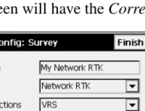
(45) Config: Survey. relative positions. If the coordinates of one receiver are known, then the coordinates of the other can be calculated. – PP Kinematic (Kinematic Post Processing) also implies two receivers. One is fixed, the other is moving along some trajectory. The processing of the collected data is performed later, as for the PP Static type. – PP DGPS (Post Processing Differential GPS) implies that the raw observations made by the rover would have to be written to files as well as the differential correction data. If the Network RTK or RT DGPS configuration is chosen for editing, the Config: Survey screen will have the Corrections field.. Figure 2-19. Config: Survey – For Network RTK. • Corrections: the type of correction data used. For the Network RTK configuration it can be VRS or FKP. For the RT DGPS configuration it can be User Based, Beacon, CDGPS, WAAS, EGNOS, OmniSTAR, or OmniSTAR HP.. TIP. TIP. If the name of Network RTK configuration has *N3 as the last three characters, Net.3 support will be activated in TopSURV. Topcon Net.3 software establishes a connection between the computer and three base receivers to form a set of corrections (Net3) used by the rover receiver. P/N 7010-0492. 2-17.
(46) Job. • Next: opens the Config: Base Receiver screen. For Network RTK and Real Time DGPS (except User Based mode), the Config: Rover Receiver screen will display next. If the PP Static type is chosen, the Config: Static Receiver screen will display next. • Finish: saves the changes and returns to the Configurations screen. For RTK survey types, the bitmap on the upper-left corner displays the pop-up menu containing two items: • MultiPort: when selected, the MultiPort functionality becomes available and the Num Ports field is added to the Config: Survey screen. • Help: accesses the Help files.. Figure 2-20. Config: Survey – MultiPort. • Num Ports: sets the number of ports to configure the Base/Rover to transmit/receive data from two different ports.. 2-18. TopSURV Reference Manual.
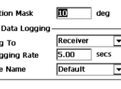
(47) Config: Survey. Config: Base (Static) Receiver For RTK, the Config: Base Receiver screen contains settings for the Base.. Figure 2-21. Config: Base Receiver. • RTK Format: the format of the base receiver differential corrections transmitted to the rover. It can be CMR, CMR+, RTCM 2.1, 2.2, 2.3, 3.0. • Elevation mask: data from satellites below this elevation will not be used. • Back: returns to the previous screen. • Next: opens the Config: Base Radio screen. • Finish: saves the changes and returns to the Configurations screen. For RTK and PP survey types, the Base Receiver (Base Recrv) screen has the following settings to record data to files:. Figure 2-22. Config: Base Receiver – For RTK & PP Survey Type. P/N 7010-0492. 2-19.
(48) Job. • RTK Format: the format of the base receiver differential corrections transmitted to the rover. It can be CMR, CMR+, RTCM 2.1, 2.2, 2.3, 3.0. • Elevation Mask: data from satellites below this elevation will not be used. • Raw Data Logging: the set of logging parameters; log to the receiver, set the logging rate and select if the name of the receiver file is automatically set or user-defined. In the latter case, the corresponding dialog box will be displayed at the logging start. • Back: returns to the previous screen. • Next: opens the Config: Base Radio screen. • Finish: saves the changes and returns to the Configurations screen. For PP Static, PP Kinematic, or PP DGPS survey types, the Config: Static (Base) Receiver screen has the same parameters as for RTK and PP survey type except the RTK Format field.. Figure 2-23. Config: Base Receiver – For PP Kinematic Survey Type. • Back: returns to the previous screen. • Next: opens the Static (Base) Antenna screen. • Finish: saves the changes and returns to the Configurations screen.. 2-20. TopSURV Reference Manual.
(49) Config: Survey. Config: Base Radio The Config: Base Radio screen contains the parameters of the radio modem connected to the Base receiver. • Radio Modem: the type of the modem. The list of pre-defined modem types changes its contents depending upon the job configuration chosen. • Receiver Port Connected to Radio: contains the parameters of the connection port: port, parity, number of data bits, baud rate, the number of stop bits. • Defaults: returns all the values in the Receiver Port Connected to Radio field to defaults. • Config Radio: displays the parameters for the chosen modem. The button changes its appearance or disappears depending upon the modem chosen.. Figure 2-24. Config: Base Radio. • Back: returns to the previous screen. • Next: opens the Base Antenna screen. • Finish: saves the changes and returns to the Configurations screen. NOTICE. NOTICE. Using Custom, AirLink GPRS, AirLink CDMA, AirLink CDPD1, CDMA2000, Sierra Wireless MP200 CDPD and. P/N 7010-0492. 2-21.
(50) Job. Internal HiPer Pro modem types does not require additional settings except the ones described. For Internal Hiper Lite • Config Radio: opens the Internal Hiper Lite screen.. Internal Hiper Lite The Internal Hiper Lite screen sets the channel number and the power of the base station’s transmitter.. Figure 2-25. Internal Hiper Lite. • Channel: sets the channel number. • Power: controls the power amplifier, either Low (250mW) or High (1W). Greater power provides for longer distance transmissions. • Link Rate: sets the data transmission rate for the RF link. • RTS/CTS: sets the data flow control • OK: returns to the Config: Base Radio screen where all settings are saved after pressing the Finish button and then transmitted when the configuration is used.. 1. CDPD stands for “Cellular Digital Packet Data”. CDPD is an open packet data service, defined as an autonomous overlay network, specified for the cellular TDMA network.. 2-22. TopSURV Reference Manual.
(51) Config: Survey. For Pacific Crest and Internal HiPer (Pacific Crest) • Config Radio: opens the Pacific Crest Radio Parms screen.. Pacific Crest Radio Parameters The Pacific Crest Radio Parms screen sets the channel number and the sensitivity of the Radio Modem.. Figure 2-26. Pacific Crest Radio Parms. • Channel: sets the operating channel to the radio modem. • Sensitivity: selects the sensitivity level for the radio modem; either low, moderate, high or off. • OK: returns to the Config: Base Radio screen. All the settings will be saved and transmitted after the Configuration will be selected for operation.. P/N 7010-0492. 2-23.
(52) Job. For Satel modems • Config Radio: opens the Satel Radio Parms screen.. Satel Radio Parameters The Satel Radio Parms screen sets the model of the Satel modem, the channel number and the frequency of the Radio Modem.. Figure 2-27. Satel Radio Parms. • OK: returns to the Base Radio screen where all the settings will be saved after the Finish button is pressed and transmitted when the configuration is used. For Internal HiPer GSM, Motorola V60 Cell Phone, Siemens TC35 Modem, Siemens M20 Modem, Nextel i58sr Cell Phone, Wavecom Fastrack GSM • Config GSM: opens the Base Cell Phone Parms screen.. Base Cell Phone Parameters The Base Cell Phone Parms screen (Figure 2-28 on page 2-25) contains a field for Base PIN input.. 2-24. TopSURV Reference Manual.
(53) Config: Survey. Figure 2-28. Base Cell Phone Parms. • OK: returns to the Base Radio screen where all the settings will be saved after the Finish button is pressed and transmitted when the configuration is used. For AirLink CDMA (Multicast UDP) • Config Multicast: opens the Base Multicast Parms screen.. Base Multicast Parameters The Base Multicast Parms screen sets IP addresses for communication between the base and several rovers using the UDP protocol.. Figure 2-29. Base Multicast Parms. • Address to add: the field for IP address input • IP addresses list: displays all IP addresses available • Delete: deletes the highlighted IP address. P/N 7010-0492. 2-25.
(54) Job. • Add: adds a new address specified in the Address to add field to the list of IP addresses • OK: returns to the Config: Base Radio screen where all the settings will be saved after the Finish button is pressed and transmitted when the configuration is used. In Multi-Port mode there will be two Config: Base Radio screens to configure radios.. Figure 2-30. Config: Base Radio1 Out. Config: Base (Static) Antenna The Config: Base Antenna (Config: Static Antenna) screen contains settings for the antenna connected to Base.. Figure 2-31. Config: Base Antenna. • Ant Type: the type of the Topcon antenna. It can be CR-3, CR-3 with Cone, CR-4, CR-4 Cone, HiPer GD/GGD, HiPer Lite/Lite+, HiPer Pro, HiPer+, Legant 2, Legant3 with UHF, Legant E, MapAnt B, MGA-1, MGA-2, Odyssey, PG-A1, PG-A1 with. 2-26. TopSURV Reference Manual.
(55) Config: Survey. ground plane, PG-A2, PG-A5, Regant-DD, Regant-SD, RegencyDD, Regency-SD, or Unknown. • Ant Ht: the height of the antenna. • Meas Type: the type of antenna height measurement; either Vertical (measuring to ARP, antenna reference point) or Slant (measuring to edge of antenna). The screen also illustrates the measurement type. • Back: returns to the previous screen. • Next: opens the Config: Rover Receiver screen. In the PP Static case, the Config: Occupation Times screen is opened. • Finish: saves the changes and returns to the Configurations screen.. Config: Rover Receiver The Config: Rover Receiver screen contains Rover settings.. Figure 2-32. Config: Rover Receiver. • RTK Format: the format of the rover receiver differential corrections received from the base; either CMR, CMR+, RTCM 2.1, RTCM 2.2, RTCM 2.3, RTCM 3.0, Full (RTCM 1,31,3) or Partial (RTCM 9,34,3). The list of pre-defined formats changes its contents depending upon the job configuration chosen. • Elevation mask: data from satellites with elevation angles below this value will not be used. • Back: returns to the previous screen.. P/N 7010-0492. 2-27.
(56) Job. • Next: opens the Config: Rover Radio screen. When within the RT DGPS configuration, the Config: Beacon, Config: WAAS, CDGPS Radio, Config: EGNOS, or Config: OmniSTAR screen will open depending on the correction type on the Config: Survey screen. • Finish: saves the changes and returns to the Configurations screen. For RTK and PP survey type, the Rover Receiver screen has the following parameters:. Figure 2-33. Config: Rover Receiver – For RTK and PP. • RTK Format: the format of the base receiver differential corrections transmitted to the rover. It can be CMR, CMR+, RTCM 2.1, 2.2, 2.3, 3.0, Full (RTCM 1,31,3), or Partial (RTCM 9,34,3). • Elevation Mask: data from satellites below this elevation will not be used. • Raw Data Logging: the set of logging parameters; log to the receiver, set the logging rate and select if the name of the receiver file is automatically set or user-defined. In the latter case, the corresponding dialog box will be displayed at the logging start. • Back: returns to the previous screen. • Next: opens the Config: Rover Radio screen. • Finish: saves the changes and returns to the Configurations screen.. 2-28. TopSURV Reference Manual.
(57) Config: Survey. For PP Kinematic or PP DGPS surveys, the Config: Rover Receiver screen has the same parameters as for RTK and PP except the RTK Format field:. Figure 2-34. Config: Rover Receiver – For PP Kinematic and PP DGPS. • Back: returns to the previous screen. • Next: opens the Config: Rover Antenna screen. • Finish: saves the changes and returns to the Configurations screen. For RTK survey types, the bitmap on the upper-left corner displays the pop-up menu containing three items: • Output Ports: sets the number of ports available for output of NMEA messages, and adds the Num Out Ports field to the Config: Survey screen.. Figure 2-35. Config: Rover Receiver – Number Out Ports. • Laser Config: when selected, the Next button opens the Laser Config screen. • Help: accesses the Help files P/N 7010-0492. 2-29.
(58) Job. Laser Config The Laser Config screen contains typical laser parameters.. Figure 2-36. Laser Config. Config: Rover Radio The Config: Rover Radio screen (Figure 2-37 on page 2-31) contains parameters for the radio modem connected to the Rover receiver. • Radio Modem: the type of modem. • Receiver Port Connected to Radio: contains the parameters of the connection port: port, parity, data, baud rate, the number of stop bits. • Defaults: returns all the values to defaults in the Receiver Port connected to radio fields. • Config Radio: displays parameters for the selected modem. The button changes its appearance or disappears depending upon the modem chosen.. 2-30. TopSURV Reference Manual.
(59) Config: Survey. Figure 2-37. Config: Rover Radio. • Back: returns to the previous screen. • Next: opens the Config: Rover Antenna screen. • Finish: saves the changes and returns to the Configurations screen. For details, see “Config: Base Radio” on page 2-21. In Multi-Port mode there will be several Config: Rover Radio screens to configure radios.. Figure 2-38. Config: Rover Radio1 In. P/N 7010-0492. 2-31.
(60) Job. Config: Beacon The Config: Beacon screen contains settings for a radio-beacon source of differential GPS corrections.. Figure 2-39. Config: Beacon. • Country: the country where the radio-beacon differential service is located. • Station: the station that provides broadcasting differential corrections for the rover. • Back: returns to the previous screen. • Next: opens the Config: Rover Antenna screen. • Finish: saves the changes and returns to the Configurations screen.. 2-32. TopSURV Reference Manual.
(61) Config: Survey. Config: WAAS The Config: WAAS screen contains settings for the WAAS source of differential correction data.. Figure 2-40. Config: WAAS. • Channel 1 and Channel 2: two receiver channels that can be allocated to WAAS satellites. • WAAS PRN #: the WAAS satellite’s PRN number. • GPS PRN #: the GPS satellite’s PRN number, which is associated with the WAAS PRN number. • Ionospheric corrections: enable/disable the use of ionospheric corrections from the WAAS satellite when computing positions: – None: ionospheric corrections are not used – Apply if avail: use ionospheric corrections if available – Use sat only if avail: use only the satellites for which ionospheric corrections are available. • Back: returns to the previous screen. • Next: opens the Config: Rover Antenna screen. • Finish: saves the changes and returns to the Configurations screen.. P/N 7010-0492. 2-33.
(62) Job. CDGPS Radio The CDGPS Radio screen contains settings for the CDGPS Radio to receive differential correction data.. Figure 2-41. CDGPS Radio. • Receiver Port Connected to Radio: contains parameters for the connection port: port, parity, number of data bits, baud rate, and the number of stop bits. • Back: returns to the previous screen. • Next: opens the Rover Antenna screen. • Finish: saves the changes and returns to the Configurations screen.. Config: EGNOS The Config: EGNOS screen contains settings for an EGNOS source of differential correction data.. Figure 2-42. Config: EGNOS. 2-34. TopSURV Reference Manual.
(63) Config: Survey. • Channel 1 and Channel 2: up to two receiver channels can be allocated to an EGNOS satellite. • EGNOS PRN #: the EGNOS satellite’s PRN number. • GPS PRN #: the GPS satellite’s PRN number, which is associated with the EGNOS PRN number. • Ionospheric corrections: enable/disable use of ionospheric corrections from the EGNOS satellite when computing positions: – None: ionospheric corrections are not used – Apply if avail: use ionospheric corrections if available – Use sat only if avail: use only the satellites for which ionospheric corrections are available. • Back: returns to the previous screen. • Next: opens the Config: Rover Antenna screen. • Finish: saves the changes and returns to the Configurations screen.. Config: OmniSTAR The Config: OmniSTAR screen contains settings for an OmniSTAR source of differential correction data.. Figure 2-43. Config: OmniSTAR. • • • •. Satellite: the satellite that delivers differential GPS corrections. Back: returns to the previous screen. Next: opens the Config: Rover Antenna screen. Finish: saves the changes and returns to the Configurations screen.. P/N 7010-0492. 2-35.
(64) Job. Config: Rover Antenna The Config: Rover Antenna screen contains settings for the antenna connected to the Rover.. Figure 2-44. Config: Rover Antenna. • Ant Type: the type of the Topcon antenna. It can be CR-3, CR-3 with Cone, CR-4, CR-4 Cone, HiPer GD/GGD, HiPer Lite/Lite+, HiPer Pro, HiPer+, Legant 2, Legant3 with UHF, Legant E, MapAnt B, MGA-1, MGA-2, Odyssey, PG-A1, PG-A1 with ground plane, PG-A2, PG-A5, Regant-DD, Regant-SD, RegencyDD, Regency-SD, or Unknown. • Ant Ht: the height of the antenna. • Meas Type: the type of the antenna height measurement; either Vertical (measure to ARP, antenna reference point) or Slant (measure to edge of antenna). The screen also illustrates the measurement type. • Back: returns to the previous screen. • Next: opens the Config: Survey Parms screen. For RTK & PP and PP Kinematic surveys, the Config: Init Times screen opens that is the same as the Config: Occupation Times screen for PP Static survey. • Finish: saves the changes and returns to the Configurations screen.. 2-36. TopSURV Reference Manual.
(65) Config: Survey. Config: Init (Occupation) Times The Config: Init (Occupation) Times screen contains timing settings for the receiver logging, used in automatic mode during a PP Static Survey, and depends upon the number of satellites available and the number of frequencies used.. Figure 2-45. Config: Occupation Times. The Config: Init (Occupation) Times screen contains settings for RTK&PP, PP Static and PP Kinematic modes. Occupation Times are the times required for ambiguity resolution (that is, the time required to estimate fixed ambiguity positions). • Num SV: the number of satellites. • Single Freq: the default occupation time in minutes for single frequency mode for a given number of satellites. • Dual Freq: the default occupation time in minutes for dual frequency mode for a given number of satellites. • Back: returns to the previous screen. • Next: proceeds to the next screen (PP Static: Config: Stakeout Parms; RTK&PP and PP Kinematic: Config: Survey Parms). • Finish: saves the changes and returns to the Configurations screen.. P/N 7010-0492. 2-37.
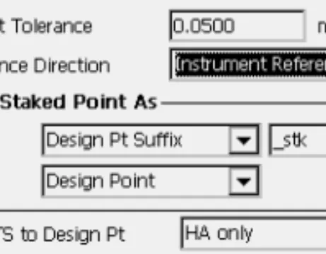
(66) Job. Config: Survey Parms The Config: Survey Parms screen sets the parameters used by default during the survey. These parameters can be changed with the help of the Settings button from any Survey screen in GPS+ mode.. Figure 2-46. Config: Survey Parms. • Solution Type: sets the solution type for each epoch. It can be “Fix Only”, “Fix and Float”, “Fix, Float, DGPS”, “DGPS”, “DGPS, Auto”, or “All”. – Fix: positions were computed by the RTK engine using the carrier phase measurements from base and rover receivers. Integer ambiguities were fixed. – Float: positions were computed by the RTK engine using the carrier phase measurements from base and rover receivers. Integer ambiguities, however, were NOT fixed (their float estimates were used instead). – DGPS: that the positions were determined using only the pseudo-range measurements or carrier-phase pseudo-ranges. – All: positions were computed using all epochs accepted, including autonomous solutions. – Auto: autonomous positions when differential corrections are not available. • The Auto Accept field sets parameters for automatic acceptance during a stationary survey. These are: – Num Meas to Avg: sets the number of measurements used for averaging, as needed.. 2-38. TopSURV Reference Manual.
(67) Config: Survey. – Precision: sets Horizontal and Vertical precision values, if to be taken into account. If both Precision and Num Meas To Avg are checked, both these conditions must be satisfied before the coordinates are accepted. • The Auto Topo field sets parameters for kinematic surveys. These are: – Method: defines the method for measuring the interval between the received epochs; by time, by horizontal distance, or by slope distance. – Interval: sets the value of this interval. For PP Kinematic or PP DGPS, the Config: Survey Parms screen displays the following parameters:. Figure 2-47. Config: Survey Parms. • Topo: enter the number of epochs to log on each location. • Auto Topo: sets the time interval between locations. Only this method is currently available. • Back: returns to the previous screen. • Next: opens the Config: Stakeout Parms screen. • Finish: saves the changes and returns to the Configurations screen.. P/N 7010-0492. 2-39.
Obraz


+7


Powiązane dokumenty
Vertical position (in pixels) of the upper left corner of the clipping planes window Default value: 150. Saved in:
In Rotan we want to be able to accept any valid set of Tm data structures as a domain, and allow a user to write transformation rules in the Rule Language instantiated for that
The existence of solu- tions for problems with Dirichlet boundary conditions is established by making use of Chang’s version of the critical point theory for non- smooth
The theory of hemivariational inequalities (as the general- ization of variational inequalities, see Duvaut & Lions, 1972) has been proved to be very useful in understanding of
Denote by M {Ω} the class of all algebras isomorphic to ones whose elements are relations and whose operations are members of Ω.. It is not finitely
Whenever τ is a type of X, the set τ −1 [0, r] can be uniformly approximated by finite unions and intersections of balls in X; furthermore, the radius of these balls can be
The generic conversion interface (see Section 6.5 [Generic Charset Conversion], page 148) does not have this limitation (it simply works on buffers, not strings), and the GNU C
We used discrete-event simulation, and animation to provide insight in the existing situation, and develop and create a shared understanding of the reference
