R
1.
is me as em th Eu ro fie tra tra ha th en Volume/TSelect
at th
as a Fun
Expe
Roland Jachi Kata. Transport
The qual an important ent. Identifica pect of activit mphasis on eco e quality of at uropean Comm nmental prote One of t eld of air qual ansport develo ansport tasks b and there is no e other hand, t nvironment (Ja Annual Ro Tom 20. Year/Rokion of a C
he Rail-roa
nction of M
enditure of
and C
imowski*, Em arzyna Marko *Warsaw U **Silesian U ***Koszalinand the env
lity of the natufactor affecti ation of the cau
ties in many ar ological forms tmospheric air mission's activ ction (Ambroz the areas of in lity improvem opment. This d between differ o difficulty in
that there are n acyna-Gołda et
Set The Environ ocznik Ochrona Ś k 2018
ontainer S
ad Intermo
Minimizat
f Transshi
CO
2Emis
milian Szczepa owska**, Janu University of T University of T University ofvironment
ural environme ing society an uses of increa reas of the eco s of business r r is a very imp vities for actio ziak et al. 2014 nterest of the ment are measudevelopment i rent modes of access to a giv no congestion t al. 2017). nment Protectio Środowiska ISSN 1506-218X
Storage Str
odal Term
tion of the
ipment De
sions
ański*, Micha usz Dąbrowsk Technology, Technology, f Technology ent, including nd, hence, eco ased emissions onomy. This is running. The w portant topic a ons taken in r 4, Jacyna et al European Com ures leading to is based on su f transport, so ven mode of tr and excessive n X 965-988rategy
minal
Energy
evices
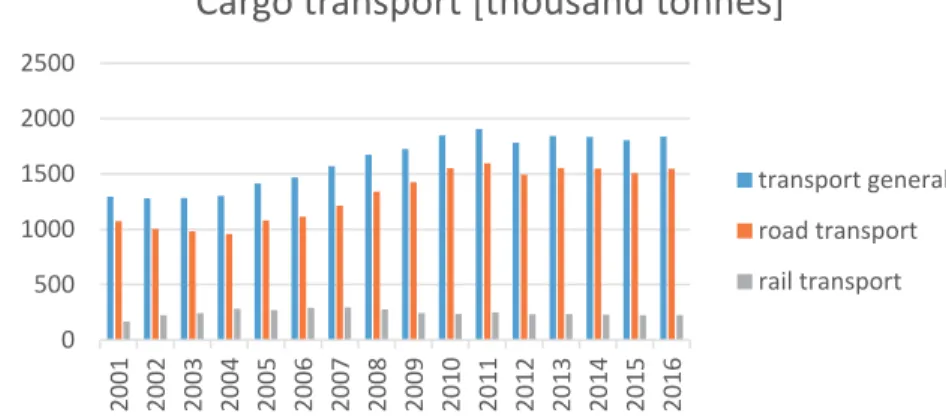
ał Kłodawski* ki*** atmospheric a onomic develo s is an importa s due to the gre work to impro and is part of t relation to env l. 2014). mmission in t o the sustainab uch a division that on the o ransport, and e pollution of t 8 *, air, op-ant eat ove the vi-the ble of one on theThe majority of environment pollutants are generated by road transport. In Poland, as much as 84% of the cargo is transported by road. For comparison, only 12% of cargo are transported by rail. 3% of cargo included in the government statistics are transported by pipeline transport, and the remaining 1% is transported by sea and inland water-way transport (Central Statistical Office 2016). Such large disproportions in terms of mass of transported cargo by road result mainly from the high availability of the road transport network and the possibility of carrying out door to door transport. Also a wide range of road transport means for transporting various types of cargo as well as the highest availability in time compared to other modes of transport results in their widespread use (Świderski et al. 2018).
The share of road transport in the total weight of transported car-go is systematically growing, as shown in Fig. 1.
Fig. 1. Share of road and rail transport in the mass of transported cargo in Poland in 2001-2016
Rys. 1. Udział transport drogowego i kolejowego w masie przewożonych ładunków w Polsce w latach 2001-2016
Predetermined for long-distance rail transport, in reality transports cargo on average distance of only 228 km. Also surprising is the average distance on which cargo are transported by road, calculated in 2016 at 196 km (Central Statistical Office 2016). Such a large and still increasing share of road transport implies undesirable effects, including air pollution from trucks' combustion engines. Therefore, the idea of sustainable
0 500 1000 1500 2000 2500 2001 2002 2003 2004 2005 2006 2007 2008 2009 2010 2011 2012 2013 2014 2015 2016
Cargo transport [thousand tonnes]
transport general road transport rail transporttransport development focuses mainly on the limitation of cargo transport by road transport towards rail, inland waterway and sea transport and multimodal solutions, as well as increasing the importance of public transport, including the increase in the share of rail vehicles in passenger transport (Jacyna-Gołda et al. 2014, Jacyna et al. 2014).
As part of the policy of sustainable transport development, in or-der to preserve the balance between various modes of transport and re-duce the negative environmental effects of transport, the European Union has taken a number of actions regarding supporting the development of intermodal transport, which is understood as the carriage of cargo using more than one type of transport and only one loading unit, e.g. container or swap body, on the entire transport route, without transshipment of the goods themselves.
These activities are described in detail in the White Paper on
Transport, where a plan to create a single european transport area was
presented with a view of reducing emissions in the transport sector by 60% by 2050. In addition, the Operational Program Infrastructure
and Environment 2014-2020 presents objectives focused at: developing
sustainable and environmentally friendly transport, improving access to the european transport network. In turn, the EU 2020 Strategy for smart
and sustainable development conducive to social inclusion assumes
supporting economies that use resources more efficiently and are more environmentally friendly.
Intermodal transport is thus considered to be a tool that will be used on a large scale to significantly reduce the emission of harmful ex-haust compounds mainly from road transport means.
Therefore, the article presents the issue of limiting the emission of harmful exhaust compounds from the point of view of the intermodal terminal operator and the transshipment loading devices powered by var-ious engines. The strategy of containers storage in the storage yard was analyzed, while also examining the distance covered by the transship-ment device and the time of carrying out the containers handling. The results obtained in a variant approach made it possible to estimate the amount of transshipment devices energy expenditure and the associated CO2 emissions. The conclusions contain recommendations for the
2. Intermodal terminals as tools for implementation
of sustainable development policy
Moving the mass of transported cargo from road transport to rail transport is closely related to the dynamic development of containerization observed since the 1980s. This is due to the growing exchange of goods in international trade and the need to look for cheap, fast and reliable forms of transport. Therefore, the possibility of transporting cargo in one loading unit offered by intermodal transport along the entire transport route using any of the transport modes is desired by trade partners.
The growing turnover of containers is a challenge for means of transport and container handling points (intermodal terminals).
According to the definition adopted by the European Conference of Ministers of Transport, ECMT), the United Nations Economic mission for Europe (UNECE) and the Organization for Economic Com-munity and Development (OECD), the terminal is an area for storage of intermodal loading units, which is equipped with transshipment equip-ment for intermodal loading units handling (ECMT).
Intermodal terminals can be divided into rail-road and marine terminals. In the first case we deal with terminals located on the railway network with access to road infrastructure. In the second case, however, these are terminals located in seaports and are part of the port. Marine intermodal terminals, due to their functions in the intermodal transport, have access to both, rail and road transport infrastructure, and in some cases, inland waterway infrastructure (Jakubowski 1978). In addition, such terminals are equipped with own warehouse facilities, which enable the provision of services related to the consolidation of general cargo in containers (Izdebski et al. 2018).
Intermodal transshipment terminals play an important role in rail-road transport, performing the following functions:
transshipment of intermodal loading units in various transition rela-tionships through the terminal. Transshipments depending on the load-ing units service technology can be carried out both directly and indi-rectly with operational storage,
operational and rotational storage of intermodal loading units,
logistic support of the transport chain (sorting of intermodal loading units, quality control, customs and border clearance),
providing additional services (current maintenance, repair and clean-ing of intermodal loadclean-ing units).
In Poland, the network of intermodal terminals is one of the densest in the European Union. The average density per area of the country is about 1 terminal per ten thousand km2. In 2016, 35 active
terminals were located in Poland: 7 marine intermodal terminals, 28 rail-road intermodal terminals.
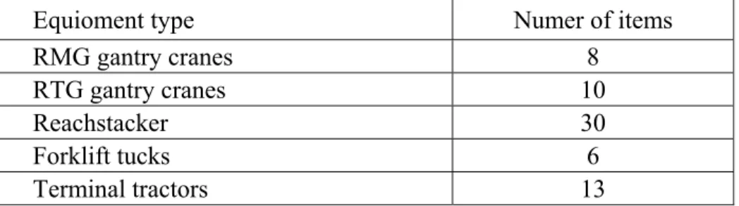
Unfortunately, the quality of their infrastructure does not go be-yond the network density of intermodal terminals. In addition to the in-sufficient length of rail loading tracks, the problem is with the handling equipment. Only few terminals are equipped with gantry cranes, allow-ing the maximum use of the cargo space and characterized by a short cycle of transshipment operations. Taking into account the number of currently operating intermodal terminals, the data included in Table 1 show their modest equipment. Detailed characteristics of transshipment equipment used in intermodal terminals are presented in work (Jacyna et al. 2017, Pyza et al. 2017).
Table 1. Equipment of the rail-road intermodal terminals in Poland
Tabela 1. Wyposażenie terminali intermodalnych kolejowo-drogowych w Polsce
Equioment type Numer of items
RMG gantry cranes 8
RTG gantry cranes 10
Reachstacker 30
Forklift tucks 6
Terminal tractors 13
The transshipment equipment mentioned in table 1, apart from the scope of container handling, also differ in their mode of power supply. In rail-road intermodal terminals, gantry cranes are powered by electricity. Other types of power supply of RTG cranes are based on a combustion engine, often acting as a power generator. Container trucks are powered only by internal combustion engines. The factors determining the use of a given transshipment equipment in an intermodal terminal are essential-ly the volume of turnover and the purchase cost of the equipment
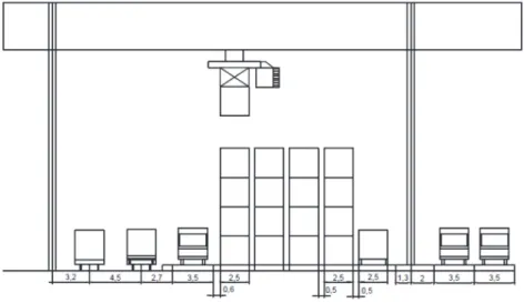
(Jacyna-Gołda et al. 2017). In large intermodal terminals, it is necessary to use gantry cranes, which in addition to significant container stacking capabilities also have the option of servicing a storage yard consisting of several rows of containers. In the case of gantry cranes, the width of the storage yard depends on the clearance between the crane supports. An exemplary cross-section of the crane operating space is shown in Fig. 2.
Fig. 2. Gantry crane operating space
Rys. 2. Przestrzeń operacyjna suwnicy bramowej
For reachstackers, the width of the storage yard will be limited to 2-3 rows of containers. The cross-section of the reachstacker operating space is shown in Fig. 3.
Fig. 3. Reachstacker operating space
3. Container storage technology in the rail-road terminal
In the rail-road intermodal terminal, after the train arrives, the wagons with containers are unloaded. The containers are transshipped directly to the road transport vehicles, or in the case of the road vehicles absence, to the storage yard. Thus, either direct or indirect loading opera-tions are performer.Due to the fact that containers at the storage yard are stacked one on top of the other, it is necessary to plan their arrangement taking into account their gross weight (heavier container should not be stored on a lighter container) stability (40' container cannot be stacked on two 20' containers and vice versa), expected date of container's departure (in or-der to avoid moving containers on the yard trying to get a given container from under another one).
The information of the container storage location in the storage yard is one of the factors determining the speed processes that are im-plemented in the intermodal terminal, which indirectly influences the success in the field of customer service. This essentially affects the dura-tion of rail cars loading / unloading operadura-tions, which in this case does not depend only on the handling equipment efficiency. At this point, a very important issue is to plan the place of containers storage after un-loading process in order to quickly load them at a later date. This issue is further complicated by the containers stacking. The time of loading oper-ations directly affects the time that train stays in the terminal.
The distribution of containers in the rail-road terminal storage yard has not been studied in the literature so far. The interest of scientists in this topic usually focuses on the distribution of containers in the stor-age yard of a marine intermodal terminal. In this area, many literature have been published. Articles regarding the containers storage can be divided into four categories:
1. Individual container distribution. 2. Distribution of groups of container.
3. Comparisons of container storage strategy.
4. Container distribution taking into account other processes in the storage area.
The distribution of individual containers on the storage yard is generally carried out in two stages (Guldogan 2010, Park et al. 2011, Chen et al. 2012). First, the container is allocated to the selected storage block and then to the selected location in the given block. This is due to the fact that in marine intermodal terminals the storage yard is divided into blocks. In rail-road terminals, there are blocks, but their division is usually resulting from different types of containers stored in these blocks. In addition, in rail-road terminals, these blocks usually constitute one large block operated by the main transshipment device.
The distribution of container groups on the yard was undertaken in the works (Nishimura et al. 2009, Huang et al. 2011, Woo et al. 2011). The allocation of container groups to the blocks usually results from the ship berthing place. In (Nishimura et al. 2009), the authors minimize the weighted total time of container handling, depending on the unloading times as well as container transport times from the berth to the storage yard. Similarly in (Huang et al. 2011) authors are using the simulated annealing algorithm to check the possible permutations of the distribution of container groups in the block. A new approach to determining the dis-tribution of container groups is proposed in paper (Woo et al. 2011). The authors have developed 4 rules of containers storage in the storage yard assuming that:
a fixed number of storage places is reserved for each container group, the containers storage time is constant. The number of free spaces in
the storage yard must correspond to the number of arriving containers, empty storage spaces are reserved in proportion to the arrival speed of containers of different groups. Thus, the number of storage places for a given container group is determined by multiplying the average con-tainer arrival rate of a given group by a fixed value,
empty storage spaces are reserved in proportion to the square roots of the number of containers arrived at the respective groups. The number of storage places for a group of containers is determined by multiply-ing the square root of the average speed of arrival of containers of a given group by a fixed value.
A part of the literature regarding the containers storage is devoted to the comparison of the storage strategies. Essentially, these strategies concern the random containers storage or according to specific categories
resulting from technical parameters of containers, dates of their departure from the storage yard or their destination for the transport of selected types of cargo. An example of such a comparison between random strat-egy and stratstrat-egy by category using simulation tools is presented in paper (Dekker et al. 2006).
The classification of container storage strategies on the storage yard was made in (Saanen et al. 2007). In turn, comparisons of these strategies were made in (Ku et al. 2010). The compared strategies are presented as follows:
Dedicated – Not dedicated. The dedicated strategy assumes that contain-ers dedicated for different ships cannot be stored in the same storage block. The „not dedicated” strategy is opposite to that, so within a given storage block different (in terms of destination) containers can be stored. Consolidated – Dispersed. The consolidated strategy groups the
contain-ers for a given ship within the storage block into clustcontain-ers. Dispcontain-ersed strat-egy does not assume such grouping. The containers are mixed up.
Housekeeping – Immediate storage. In the housekeeping strategy, the containers in the storage block are placed temporarily. In the metime, before the planned departure, the container is moved to the an-other area of a given block or to anan-other block, in order to accelerate its later loading onto the means of external transport. In the strategy of immediate storage, the container after delivery to the storage block remains in a given place until its departure.
Storage optimization – Handling (loading) optimization. In the storage optimization, the container is placed in a block in order to maximize the efficiency of the storage space utilization. In the handling optimi-zation strategy, the container is placed in a storage block in order to enable its later loading in a shorter time.
The above-mentioned strategies were investigated in papers (Bruzzone et al. 1998, Petering et al. 2006, Saanen et al. 2007, Stahlbock et al. 2008, Zhang et al. 2003, Kim et al. 2006). Literature analysis of the above strategies has shown that there is a lot of space devoted to the problem of housekeeping container storage. This is due to the specific requirements of sea carriers, which within the contracts with intermodal terminals reserve the preferred storage locations for their containers, in order to minimize their vessels unloading / loading time.
The part of the literature regarding container storage at the inter-modal terminal captures this problem comprehensively in connection with terminal transport processes. For example, in (Lee et al. 2006) the authors consider the issue of container storage from the point of view the total number of crane cycles minimization. On the other hand, in the works (Murty et al. 2005, Murty et al. 2005) the authors developed deci-sion support systems in which the problem of container storage was con-nected to the problem of container transport in the terminal, the alloca-tion of gantry cranes for containers handling as well as the road vehicles arrival scheduling.
The similar approach was presented in paper (Laik et al. 2008). Using the simulation approach as well as the consolidated strategy, the problem of container storage and crane scheduling from the point of view of minimization of storage and handling costs were considered.
Combinations of container storage problems with the problem of their transport from the quay to the storage yard were made in (Lee et al. 2012).
4. Problem description
In this article, the authors consider the problem of the containers distribution in the storage yard. We focus on various strategies for the containers distribution in the storage yard, depending on the arrangement of containers on the train. It was proposed to analyze the distance trav-eled by the loading device (crane) during the loading operations in the wagon-yard relation depending on whether the containers are placed on the yard relative to their size or container’s owner with different contain-er distribution strategies on the rail cars.
A review of the literature in the field of container storage at ma-rine terminal suggests, that only the optimization algorithms used there can be also used in rail-road terminals. This is obviously due to the speci-ficity of the rail-road intermodal terminal. In principle, only strategies such as: dedicated and consolidated after taking into account certain modifications allow their use in the rail-road terminal. These modifica-tions concern the division of the containers storage yard into areas of containers of individual sizes or, alternatively, dividing the storage yard into the areas where the containers of sea or rail carriers are stored. The consolidated and dedicated strategy in its pure form would indicate the
need to place containers intended for a given train in one place (area) of the storage yard. However, due to the considerable length of the inter-modal train, preparation of containers intended for a given interinter-modal train in one area will generate unnecessary extended distances that a loading device must overcome in order to deliver a container for a car located even several hundred meters away from the temporary container storage area. In fact, in small rail-road intermodal terminals with relative-ly small containers flow (eg terminals serving one intermodal train per day), this practice is followed. In the case of such a small workload, the terminal can afford this type of practice, which is inappropriate from an economic point of view.
Regarding the above, the article presents an analysis of the strate-gies for the distribution of import containers in the storage yard, while taking into account their distribution on the train. The container storage distribution strategies analyzed in this paper are:
a) containers distribution in the storage yard by their size, b) containers distribution in the storage yard by their owners
(sea or rail carriers).
In addition to the distribution of containers on the storage yard, we also analyzed the distribution of these containers on the train and its impact on the distance traveled by the loading device depending on the strategy. The strategies of containers distribution on a train generally assume:
a) random distribution of containers on the train,
b) distribution of containers on the train according to their owners (sea or rail carriers).
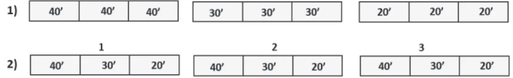
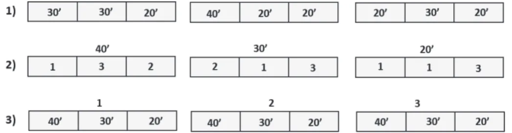
As a result, in the article we proposed the following variants of the containers distribution on the yard:
1. Distribution by container size. Starting from the head of the train, con-tainers 40', 30' and finally 20' are placed in the yard.
2. Distribution according to container owners and containers size at the same time. Starting from the head of the train, the containers of the owner 1, 2 and 3 are placed. In addition, the containers of individual owners are set in the order 40', 30' and 20'.
The above variants of the containers distribution on the yard are schematically shown in Fig. 4 ((1) – variant number, 20' – container size, 1, 2, 3 – container owner number). The storage yard in these vari-ants has been divided into areas where the containers are generally stored by their size or by owner and size.
Fig. 4. Containers storage variants
Rys. 4. Warianty przechowywania kontenerów
The variants of containers distribution on train are presented as follows:
1. Random containers distribution.
2. Distribution of containers according to their size with random assign-ment of container owners. From the head of the train containers 40', then 30' and finally 20' are placed on the cars. In addition, distribution of containers of individual owners within containers of a given size is random.
3. Distribution of containers according to their owners and size. Starting from the head of the train, the containers belonging to the owner 1, 2 and 3 are placed. In addition, the containers of individual owners are set by their decreasing size (first the 40' containers of the owner 1, then 30' a 20' containers of the owner 1).
The above variants of containers distribution on the train are shown in Fig. 5 ((2) – variant number, 20' – container size, 1, 2, 3 – tainer owner number). The train was divided into parts in which the con-tainers were distributed randomly, by size or by their owner.
Considering the problem of the distance covered by the loading device (gantry crane), the above three variants of container distribution on the train were analyzed together with two variants of the containers distribution on the storage yard. As a result, 5 variants were obtained, which were analyzed using a simulation tool. These variants are summa-rized in the Table 2.
Fig. 5. Variants of containers distribution on train Rys. 5. Warianty rozmieszczenia kontenerów w pociągu
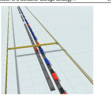
For the purposes of the research, a simulation model of containers transshipment process from the train to the storage yard was developed. The model was built in FlexSim environment. It is a software that allows for intuitive mapping and optimization of any transport processes, re-gardless of their scale. Thanks to the extensive library of 3D objects, it is possible to reproduce the analyzed process (eg the movement of a con-tainer through an intermodal terminal). In addition, the ability to visual-ize the process allows for even more accurate mapping and analysis.
Table 2. Variants numbers of containers distribution on the train and on the storage yard
Tabela 2. Warianty rozmieszczenia kontenerów na pociągu i placu składowym
Variant
1 2 3 4 5
Number of a variant of containers
distribution on train 1 2 3 2 3
Number of a variant of containers
distribution on storage yard 1 1 1 2 2
To conduct analyzes, the following assumptions were necessary: Containers ISO 1A, 1B and 1C were the subject of the research. Containers belong to 3 different owners.
The number of containers by their size and owners is presented in Table 3.
The trains consists of 30 cars. Every car is 19,9 m long and has 3 TEU capacity.
Containers were stored in one layer in the first row of the storage block. The distance between the rail cars and the storage yard was 6 m. Konecranes RTG gantry crane was used as a loading device. This
choice was dictated by the quite common use of this type of gantry at rail-road intermodal terminals. Its technical parameters relevant to the covered distance are shown in Table 4.
Rail cars are unloaded starting from the first car at the head of in the train according to the FIFO strategy.
Unloading was carried out by a single gantry crane powered by elec-tricity.
The average time of container capture was 15 s. The average time of container release was 25 s.
Table 3. Number of containers by their size and owners Tabela 3. Liczba pojemników według wielkości i właścicieli
Container type Owner number Total
1 2 3
1C 8 8 8 24
1B 3 3 2 8
1A 6 5 5 16
Total 48
Table 4. Konecranes RTG crane technical parameters
Tabela 4. Parametry techniczne żurawia typu Konecranes RTG
Parameter Value m/s
Lifting/ lowering speed 0,43
Trolley speed 1,16
Gantry speed 2,16
Schematically, a fragment of the constructed simulation model is shown in Fig. 6.
Fig. 6. A fragment of the simulation model prepared in the FlexSim tool
Rys. 6. Fragment modelu symulacyjnego przygotowanego w narzędziu FlexSim
5. Results
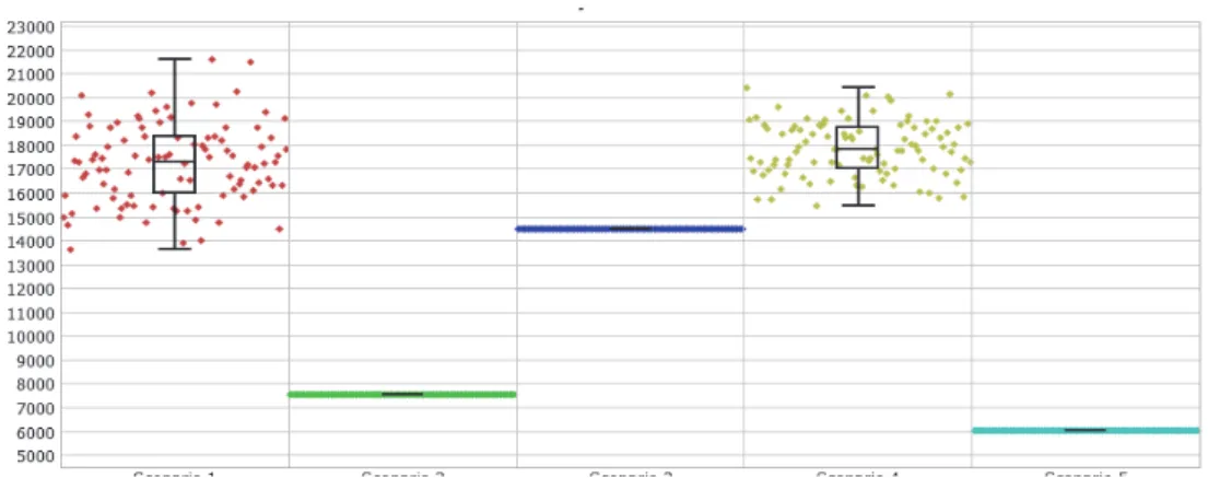
Due to the random distribution of containers on rail cars in some variants, computational experiments were performed for 100 random samples. The results of the obtained calculations are shown in Fig. 7. The minimum value of the distance covered by the loading device (6025 m) was obtained for variant 5. The analysis of the results indicates that the variants, where the random distribution of containers on the cars was allowed, turned out to be worse than the others from the point of view of the distance covered by the loading device (crane).
In addition to the distance traveled by the device, the times of carrying out loading operations in individual variants were also calculated (see Table 5). These times were used to calculate the energy expenditure of the loading device. Based on the data from the crane manufacturer (CONECRANES Catalog), it was assumed that, when the crane's loading capacity is fully utilized, its hourly electricity consumption is 99 kWh. Therefore, the energy expenditure related to container loading in individual variants is presented in Table 5.
Fig. 7. Experiments results with the use of the FlexSim tool (distances in meters)
Rys. 7. Wyniki eksperymentów w programie FlexSim (odległość w metrach)
In addition to supplying RTG cranes with electricity from an intermodal terminal electricity network, manufacturers also offer more mobile solutions using an internal combustion engine. These types of gantries are usually used in storage yards in marine intermodal terminals, where cranes often change their working area (in this case, permanent connection of the crane with an electric cable would be troublesome). The mobile solutions of the RTG cranes include the use of only an internal combustion engine or a hybrid engine for powering the crane. From the point of view of crane operating costs, as well as the negative impact of harmful exhaust compounds on the natural environment, the use of this type of power supply is uneconomical and not ecological. In order to present differences in energy expenditure for different types of crane power supply, their comparison for the model considered in the article was made in table 6. Based on the manufacturer's data, the hourly fuel consumption was assumed in a crane powered by a hybrid and combustion engine, respectively 19 and 26 liters.
Table 5. Konecranes RTG energy expenditure in a given variant Tabela 5. Wydatek energetyczny Konecranes RTG w danym wariancie
Variant
1 2 3 4 5
Containers loading time [s] 9901 6444 9684 12410 5755 Energy consumption [kWh] 272,278 177,21 266,31 341,275 158,2625
Table 6. Konecranes RTG energy expenditure Tabela 6. Wydatki energetyczne Konecranes RTG
Variant
1 2 3 4 5
Containers loading time [s] 9901 6444 9684 12410 5755 Electric crane
(electricity consumption [kWh]) 272,28 177,21 266,31 341,28 158,26 Hybrid crane
(diesel consumption [liters]) 52,26 34,01 51,11 65,50 30,37 Diesel crane
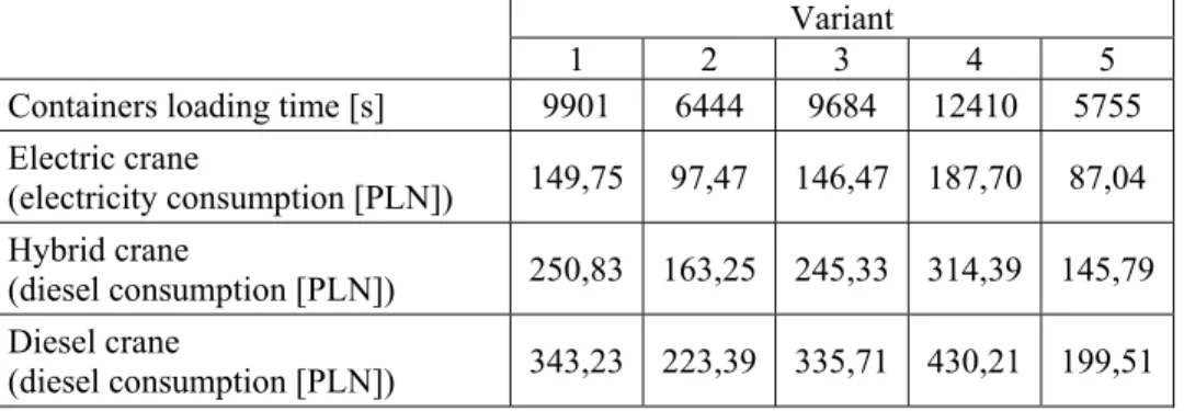
(diesel consumption [liters]) 71,51 46,54 69,94 89,63 41,56 Based on the energy consumption, the costs of particular types of cranes use were calculated assuming that: the price of 1 kWh of electrici-ty is PLN 0.55, and the cost of 1L diesel is PLN 4.8. The results of the calculations are summarized in Table 7.
Table 7. Konecranes RTG power supply costs Tabela 7. Koszty zasilania Konecranes RTG
Variant
1 2 3 4 5
Containers loading time [s] 9901 6444 9684 12410 5755 Electric crane (electricity consumption [PLN]) 149,75 97,47 146,47 187,70 87,04 Hybrid crane (diesel consumption [PLN]) 250,83 163,25 245,33 314,39 145,79 Diesel crane (diesel consumption [PLN]) 343,23 223,39 335,71 430,21 199,51
Based on the above table it is clear that the cost of using of crane powered by an internal combustion engine is more than twice as high as in the case of a crane powered from electricity network. In addition to the high cost of operation, this type of equipment also emits significant amounts of carbon dioxide into the atmosphere. For the purpose of calcu-lation of the CO2 emission generated by the gantry cranes in the analyzed
model, it was assumed that (Geerlings et al. 2011): 1L of diesel generates 2.65 kg of CO2,
production of 1 kWh of electricity by a power plant is related to the generation of 0.52 kg of CO2 into the atmosphere.
The calculations were carried out for gantry cranes powered by electric energy and those equipped with a combustion and hybrid engine. The results of calculations are summarized in Table 8.
Table 8. Konecranes RTG CO2 emission Tabela 8. Emisja CO2 Konecranes RTG
Variant
1 2 3 4 5
CO2 emission
form the electric crane [kg] 141,58 92,15 138,48 177,46 82,30 CO2 emission
form the hybrid crane [kg] 133,77 87,07 130,84 167,67 77,76 CO2 emission
form the diesel crane [kg] 183,06 119,14 179,05 229,45 106,40
The results presented in the above table interpreted from the point of view of the negative impact of transport on the environment minimiza-tion show that the hybrid crane seems to be the most environmentally friendly. Taking into account the CO2 emissions generated by power
plants producing electricity, the use of gantry cranes powered only by an electric motor is not as environmentally friendly as it might seem. Never-theless, from the point of view of the intermodal terminal owner the elec-tric gantry crane will be most desirable mainly due to the significantly lower operating costs of the device resulting from the electricity con-sumption.
6. Summary
The research carried out in the article using a simulation model in the FlexSim environment and their results indicate the need for a struc-tured planning of the distribution of containers on the storage yard and on the train. The values of the distance traveled by the loading device in particular variants differ significantly depending on whether the distribu-tion of containers on the train was planned or not. Variants allowing the random distribution of containers on the train were much worse than those where the distribution was planned, while planning the distribution of containers on the terminal yard. The time of containers handling in random variants was almost twice as long as the time obtained in the best variant. Only variant 3 proved to be comparable with the best results for random variants. Based on the calculations, it was found that distribution of containers on the yard and on the train with respect to their owners and size is reasonable. At the same time, testing of CO2 emissions of the
loading device indicated that from the point of view of CO2 minimization
it is better to use cranes powered by a hybrid engine.
References
Ambroziak, T., Pyza D., Merkisz-Guranowska, A., Jachimowski R. (2014). Ocena
wpływu transportu drogowego na degradację środowiska przy różnej struktu-rze pojazdów. Oficyna Wydawnicza Politechniki Warszawskiej, Warszawa.
Bruzzone, A., Signorile, R. (1998). Simulation and genetic algorithms for ship planning and shipyard layout. Simulation, 71(2), 74-83.
Central statistical office (2016) – Transport results of operations.
Chen, L., Lu, Z. (2012). The storage location assignment problem for outbound containers in a maritime terminal. International Journal of Production
Economics, 135(1), 73-80.
CONECRANES Catalog available at www.konecranes.com
Dekker, R., Voogd, P., Van, Asperen, E. (2006). Advanced methods for con-tainer stacking. OR Spectrum, 28, 563-586.
Europejska Konferencja Ministrów Transportu ECMT
Geerlings, H., Duin, R. (2011). A new method for assessing CO2-emissions
from container terminals: a promising approach applied in Rotterdam,
Journal of Cleaner Production, 19(6-7).
Guldogan, E. (2010). Simulation-based analysis for hierarchical storage as-signment policies in a container terminal. Simulation, 87(6), 523-537.
Huang, J., Ren, Z. (2011). Research on SA-based addressing model of slot in container terminal. Applied Mechanics and Materials, 97-98, 985-989. Izdebski, M., Jacyna-Gołda, I., Wasiak, M., Jachimowski, R., Kłodawski, M.,
Pyza D., Żak, J. (2018). The application of the genetic algorithm to multi-criteria warehouses location problems on the logistics network. Transport,
33(3), 741-750.
Jacyna, M., Jachimowski, R., Pyza D. (2017). Transport Intermodalny.
Projek-towanie terminali przeładunkowych. PWN, Warszawa.
Jacyna, M., Merkisz, J. (2014). Proecological approach to modelling traffic or-ganization in national transport system. Archives of Transport, 30(3), 31-41. Jacyna, M., Wasiak, M., Lewczuk, K., Kłodawski, M. (2014). Simulation model
of transport system of Poland as a tool for developing sustainable transport.
Archives of Transport, 31(3), 23-35.
Jacyna-Gołda, I., Żak, J., Gołębiowski, P. (2014). Models of traffic flow distri-bution for various scenarios of the development of proecological transport system. Archives of Transport, 33(1), 17-28.
Jacyna-Gołda, I., Lewczuk, K. (2017). The method of estimating dependability of supply chain elements on the base of technical and organizational re-dundancy of process. Maintenance and Reliability, 19(3), 382-392.
Jacyna-Gołda, I., Gołębiowski, P., Izdebski, M., Kłodawski, M., Szczepański, E. (2017). The evaluation of the sustainable transport system development with the scenario analyses procedure. Journal of Vibroengineering, 19(7), 5627-5638.
Jakubowski, L. (1978). Punkty kontenerowe w transporcie lądowym. Wydaw-nictwo Komunikacji i Łączności, Warszawa.
Kim, KH., Kim, H.B. (2006). The optimal sizing of the storage space and han-dling facilities for import containers. Transportation Research Part B, 36B, 821-835.
Ku, L.P., Lee, L.H, Chew, E.P., Tan, K.C. (2010). An optimization framework for yard planning in a container terminal: Case with automated rail-mounted gantry cranes. OR Spectrum, 32(3), 519-542.
Laik, N., Hadjiconstantinou, E. (2008). Container assignment and gantry crane deployment in a container terminal: A case study. Maritime Economics &
Logistics, 10, 90-107.
Lee, D.H., Jin, J.G., Chen, J.H. (2012). Schedule template design and storage allocation for cyclically visiting feeders in container transshipment hubs.
Transportation Research Record, 2273, 87-95.
Lee, L.H., Lee, E.P. Chew, CHEW, Tan, K.C., TAN, Han, Y. (2006). An opti-mization model for storage yard management in transshipment hubs. OR
Murty, K.G., Wan, Y.W., Liu, J, Tseng, M.M., Leung, E., Lai, K.K., Chiu, W.C. (2005). Hong Kong International Terminals gains elastic capacity us-ing a dataintensive decision-support system. Interfaces, 35(1), 61-75. Murty, K.G., Liu, J., Wan, Y.W., Linn, R. (2005). A decision support system for
operations in a container terminal. Decision Support Systems, 39, 309-332. Nishimura, E., Imai A., Janssens, G.K., Papadimitriou, S. (2009). Container
storage and transshipment marine terminals. Transportation Research Part E, 45, 771-786.
Park, T., Choe, R., Kim, Y.H., Ryu, K.R. (2011). Dynamic adjustment of con-tainer stacking policy in an automated concon-tainer terminal. International
Journal of Production Economics, 133, 385-392.
Petering, M.E., Murty, K.G. (2006). Simulation analysis of algorithms for con-tainer storage and yard crane scheduling at a concon-tainer terminal. In:
Pro-ceedings of the second international intelligent logistics systems confer-ence, Brisbane, Australia, 19.1-19.15.
Pyza, D., Jachimowski, R., Jacyna-Gołda, I., Lewczuk, K. (2017). Performance of equipment and means of internal transport and efficiency of implemen-tation of warehouse processes. Procedia Engineering, 187, 706-711. Saanen, Y.A., Dekker, R. (2007) Intelligent stacking as way out of congested
yards? part 1. Port Technol Int, 31, 87-92.
Sanen, Y.A., Dekker, R. (2007). Intelligent stacking as way out of congested yards? part 2. Port Technol Int 2007, 32, 80-85.
Stahlbock, R., Voß, S. (2008). Operations research at container terminal: a liter-ature update. OR Spectrum 2008, 30, 1-52.
Świderski, A., Jóźwiak, A., Jachimowski, R. (2018). Eksploatacyjne miary ja-kości pojazdów w zastosowaniu do oceny usług transportowych z wyko-rzystaniem sztucznych sieci neuronowych. Eksploatacja i Niezawodnosc -
Maintenance and Reliability, 2, 292-299.
Woo, Y. J., Kim, K.H. (2011). Estimating the space requirement of outbound container inventories in port container terminals. International Journal of
Production Economics, 133, 293-301.
Zhang, C., Liu, J., Wan, Y.W., Murty, K.G., Linn, R. (2003). Storage space allocation in container terminals. Transportation Research Part B, 37B, 883-903.
Dobór strategii składowania kontenerów w lądowym
terminalu intermodalnym w funkcji minimalizacji
wydatku energetycznego urządzeń przeładunkowych
i emisji CO
2 StreszczenieW artykule przedstawiono problematykę składowania kontenerów na placu składowym w lądowym terminalu intermodalnym i związaną z tym emisją szkodliwych związków spalin do atmosfery. Zagadnienie to rozważano z punktu widzenia dystansu pokonywanego przez urządzenia ładunkowe, czasu trwania prac ładunkowych oraz wynikającego z tego wydatku energetycznego i emisją
CO2. Przeprowadzone badania podyktowane były dotychczasową niewielką
licz-bą publikacji na temat badania rozmieszczenia kontenerów na placach składo-wych w lądoskłado-wych, kolejowo-drogoskłado-wych terminala intermodalnych. Zdecydowa-na większość literatury poświęcoZdecydowa-na jest w tym zakresie morskim termiZdecydowa-nalom intermodalnym, których charakterystyka pracy różni się od tej w terminalach lądowych. Wskazano także na istotność tego problemu wynikającą z rosnących obrotów kontenerów przewożonych transportem kolejowym. Systematyczny wzrost tych przewozów i wyczerpywanie się zdolności obsługowych terminali intermodalnych powoduje konieczność usprawniania zachodzących tam proce-sów. Możliwość usprawniania tych procesów oprócz zastosowania narzędzi komputerowych realizowana jest także dzięki wykorzystaniu nowoczesnych urządzeń przeładunkowych. Urządzenia te w zależności od obszaru ich działania i zakresu ich zastosowania wykorzystują różne rodzaje zasilania, które w więk-szym, bądź mniejszym stopniu wpływają na zanieczyszczenia środowiska. W przypadku rozważanych w niniejszym artykule suwnic jezdniowych, zasilanie to pochodzić może zarówno z silników spalinowych, hybrydowych jak i silników elektrycznych. Stąd też z punktu widzenia minimalizacji wielkości emisji szko-dliwych związków spalin do atmosfery w artykule podjęto także problematykę wyboru urządzenia do realizacji zadań przeładunkowych.
Na potrzeby badań szczegółowo przedstawiono procesy obsługi konte-nera w lądowym terminalu intermodalnym. Dokonano przeglądu literatury w zakresie metod i strategii składowania kontenerów. Rozważane procesy prze-ładunku kontenerów w relacji wagon-plac składowy zamodelowano w środowi-sku symulacyjnym FlexSim. Zbudowany model symulacyjny posłużył do opra-cowania 5 wariantów rozmieszczenia kontenerów na placu w funkcji ich roz-mieszczenia na pociągu. Badania rozroz-mieszczenia kontenerów na placu składo-wym wykonywano zarówno dla losowego jak i ustalonego rozmieszczenie
kon-tenerów na pociągu. W przypadku losowego rozmieszczenia konkon-tenerów na pociągu próby wykonywano dla 100 powtórzeń.
Na podstawie badań symulacyjnych określono dystans pokonywany przez urządzenie przeładunkowe (suwnicę RTG) oraz czas realizacji prac ła-dunkowych w poszczególnych wariantach. Wykorzystując podawane przez producenta suwnic dane o wielkości zużywanej przez suwnicę energii obliczono jej wydatek energetyczny w poszczególnych wariantach dla różnych sposobów zasilania (silnik spalinowy, hybrydowy, elektryczny).
Uzyskane wyniki pozwoliły na wybór najlepszej spośród rozważanych, strategii składowania kontenerów na placu przy uwzględnieniu wielkości
emi-towanego przez urządzenia przeładunkowe CO2 do atmosfery.
Abstract
The article presents the problem of containers storage on a storage yard in an rail-road intermodal land and the emission of harmful exhaust gases into the atmosphere. This issue was considered from the point of view of the dis-tance traveled by transshipment devices, the duration of loading work and the
resulting energy expenditure and CO2 emissions. The research was dictated by
the current limited number of publications in the area of the distribution of con-tainers on storage yards in rail-road intermodal terminals. The vast majority of the literature is devoted in this field to marine intermodal terminals, which op-erating characteristics are different from inland terminals. The importance of this problem resulting from the growing turnover of containers transported by rail transport was also pointed out. The systematic increase of this type of trans-port and the depletion of the intermodal services' operating capability makes it necessary to improve the processes taking place in the storage area. The possi-bility of improving these processes in addition to the use of computer tools is also realized through the use of modern transshipment devices. Depending on the area of their operation and the scope of their application, these devices use various types of power supply, which affect environmental pollution. In the case of gantry cranes considered in this article, their power supply may come from both combustion engines, hybrids and electric engines. Therefore, from the point of view of minimization of harmful exhaust gases emissions into the at-mosphere, in the article, the problem of choosing the device for carrying out transshipment tasks was also taken up.
For the purposes of the research, the processes of container handling in the rail-road intermodal terminal have been presented in detail. A review of literature in the field of container storage methods and strategies was carried out. The considered container reloading processes in the wagon-yard relation were modeled in the FlexSim simulation environment. The constructed
simula-tion model was used to develop 5 variants of the distribusimula-tion of containers on the storage yard as a function of their location on the train. Container deploy-ments on the storage yard were carried out for both random and fixed distribu-tion of containers on the train. In the case of a random arrangement of contain-ers on the train, the tests were carried out for 100 replications.
On the basis of simulation tests, the distance covered by the transship-ment device (RTG crane) and the time of carrying out the loading tasks in par-ticular variants were determined. Using the crane data provided by the crane manufacturer, the energy expenditure was calculated in individual variants for different power supply methods (combustion engine, hybrid, electric engine).
The obtained results allowed the selection of the best strategy for
con-tainers storage, taking into account the amount of CO2 emitted to the
atmos-phere by transshipment devices. Słowa kluczowe:
Transport intermodalny, terminal intermodalny kolejowo-drogowy,
strategie składowania kontenerów, emisja CO2, analiza symulacyjna, FlexSim
Keywords:
Intermodal transport, rail-road intermodal terminal,