GLOBAL POSITIONING SYSTEM
STANDARD POSITIONING SERVICE
PERFORMANCE STANDARD
4
th
Edition
September 2008
I n t e g r i t y - S e r v i c e - E x c e l l e n c e
TABLE OF CONTENTS
List of Figures
……… iii
List of Tables
……..……… iii
List of Appendixes
……… iv
Executive Summary
………. v
SECTION 1.0 The GPS Standard Positioning Service ... 1
1.1 Purpose ... 1
1.2 Scope ... 2
1.3 GPS SPS Definition ... 3
1.4 Key Terms and Definitions ... 3
1.5 Global Positioning System Overview ... 3
1.5.1 GPS Space Segment ... 3
1.5.2 GPS Control Segment ... 5
SECTION 2.0 SPS SIS Characteristics and Minimum
Usage Assumptions ... 7
2.1 SPS SIS Interface Specification Requirements ... 7
2.2 Overview of SPS SIS Interface Characteristics ... 7
2.2.1 SPS SIS RF Characteristics ... 7
2.2.2 GPS NAV Message Characteristics ... 8
2.3 Overview of SPS SIS Performance Characteristics ... 9
2.3.1 SPS SIS Availability ... 9
2.3.2 SPS SIS Health... 9
2.3.3 SPS SIS Accuracy ... 11
2.3.4 SPS SIS Integrity ... 11
2.3.5 SPS SIS Continuity ... 13
2.3.6 SPS SIS UTC(USNO) Accuracy ... 13
2.4 Usage Assumptions for SPS Performance Standards ... 13
2.4.1 SPS User ... 13
2.4.2 C/A-Code ... 13
2.4.3 Single-Frequency Operation ... 13
2.4.4 SPS SIS Health... 14
2.4.5 Excluded Errors ... 15
SECTION 3.0 SPS SIS Performance Standards ...16
3.1 Overview ... 16
3.2 24-Slot Constellation Definitions ... 17
3.3 SPS SIS Coverage... 19
3.3.1 Per Satellite Coverage ... 19
3.4 SPS SIS Accuracy ... 21
3.4.1 SPS SIS URE Accuracy Standards ... 21
3.4.2 SPS SIS URRE Accuracy Standards ... 23
3.4.3 SPS SIS URAE Accuracy Standards ... 23
3.4.4 SPS SIS UTCOE Accuracy Standards ... 24
3.5 SPS SIS Integrity ... 25
3.5.1 SPS SIS Instantaneous URE Integrity Standards ... 25
3.5.2 SPS SIS Instantaneous URRE Integrity Standards... 26
3.5.3 SPS SIS Instantaneous URAE Integrity Standards ... 26
3.5.4 SPS SIS Instantaneous UTCOE Integrity Standards ... 27
3.6 SPS SIS Continuity ... 28
3.6.1 SPS SIS Continuity Standards – Unscheduled Failure Interruptions ... 28
3.6.2 SPS SIS Continuity Standards – Unscheduled Maintenance Interruptions ... 28
3.6.3 SPS Status and Problem Reporting Standards ... 29
3.7 SPS SIS Availability ... 30
3.7.1 SPS SIS Per-Slot Availability Standards ... 30
3.7.2 SPS SIS Constellation Availability Standards ... 31
3.7.3 Operational Satellite Count Standards ... 32
3.8 SPS Position/Time Domain Standards ... 33
3.8.1 PDOP Availability Standards ... 33
3.8.2 SPS Position Service Availability Standards ... 34
3.8.3 SPS Position/Time Accuracy Standards ... 34
SECTION 4.0 References ...35
4.1 Government Documents ... 35
List of Figures
Figure 1.5-1 GPS SIS Generation and Transmission ... 4
Figure 1.5-2 The GPS Operational Control System ... 5
Figure 2.2-1 NAV Message Content and Format Overview ... 8
List of Tables
Table 3.2-1 Baseline 24-Slot Constellation Slot Assignments as of the Defined Epoch ... 17Table 3.2-2 Expandable 24-Slot Constellation Slot Assignments as of the Defined Epoch ... 18
Table 3.2-3 Reference Orbit Parameters ... 18
Table 3.3-1 SPS SIS Per-Satellite Coverage Standards ... 19
Table 3.3-2 SPS SIS Constellation Coverage Standards ... 20
Table 3.4-1 SPS SIS URE Accuracy Standards ... 22
Table 3.4-2 SPS SIS URRE Accuracy Standards ... 23
Table 3.4-3 SPS SIS URAE Accuracy Standards ... 23
Table 3.4-4 SPS SIS UTCOE Accuracy Standards ... 24
Table 3.5-1 SPS SIS Instantaneous URE Integrity Standards ... 25
Table 3.5-2 SPS SIS Instantaneous URRE Integrity Standards ... 26
Table 3.5-3 SPS SIS Instantaneous URAE Integrity Standards ... 26
Table 3.5-4 SPS SIS Instantaneous UTCOE Integrity Standards ... 27
Table 3.6-1 SPS SIS Unscheduled Failure Interruption Continuity Standards ... 28
Table 3.6-2 SPS SIS Unscheduled Maintenance Interruption Continuity Standards ... 28
Table 3.6-3 SPS Status and Problem Reporting Standards ... 29
Table 3.7-1 SPS SIS Per-Slot Availability Standards ... 30
Table 3.7-2 SPS SIS Constellation Availability Standards ... 31
Table 3.7-3 Operational Satellite Count Standards ... 32
Table 3.8-1 PDOP Availability Standards ... 33
Table 3.8-2 SPS Position Service Availability Standards ... 34
List of Appendixes
Appendix A: SPS Signal-In-Space (SIS) Background Information
Appendix B: SPS Position, Velocity, and Time (PVT) Performance Expectations
Appendix C: Key Terms, Definitions, Abbreviations and Acronyms
Executive Summary
The U.S. Global Positioning System (GPS) Standard Positioning Service (SPS) consists of space-based positioning, navigation, and timing (PNT) signals delivered free of direct user fees for peaceful civil, commercial, and scientific uses worldwide. This SPS Performance Standard (SPS PS) specifies the levels of SPS performance in terms of broadcast signal parameters and GPS constellation design. The U.S. Government is committed to meeting and exceeding the minimum levels of service specified in this SPS PS and this commitment is codified in U.S. Law (10 U.S.C. 2281(b)).
Since GPS initial operational capability (IOC) in 1993, actual GPS performance has continuously met and exceeded minimum performance levels specified in the SPS PS and users can generally expect improved performance over the minimum levels described here. For example, with current (2007) Signal-in-Space (SIS) accuracy, well designed GPS receivers have been achieving horizontal accuracy of 3 meters or better and vertical accuracy of 5 meters or better 95% of the time. A number of U.S. agencies continually monitor actual GPS SPS performance, including the Federal Aviation Administration (FAA) which publishes quarterly Performance Analysis Reports at its National Satellite Test Bed (NSTB) web site (http://www.nstb.tc.faa.gov/). Interested readers are encouraged to refer to this and other sources for updated GPS performance. As an additional example of improved U.S. commitments to the worldwide GPS user community, the U.S. President announced in 2007 that Selective Availability will not be built into modernized GPS III satellites.
Although GPS will provide three new modernized civil signals in the future: L2C, L5, and L1C, the performance specifications in this version of the SPS PS apply only to users of the L1 (1575.42 MHz) Coarse/Acquisition (C/A) signal, since this is the only civil GPS signal that has reached full operational capability at this time. Furthermore, an “Expandable 24-Slot” GPS constellation with more than 24 satellites is introduced in this document and the “Baseline 24-Slot” GPS constellation definition remains unchanged from the previous version of the SPS PS.
The SPS PS will be updated periodically as GPS modernizes its civilian services. This version of the SPS PS revises and supersedes the previous version, published 4 October 2001, and meets or surpasses all the performance commitments of the previous version. Significant changes to this update include a 33% improvement in the minimum level of SIS range accuracy, from 6 meters root mean square (rms) accuracy to 4 meters rms (7.8 meters 95%), as well as the addition of minimum levels of SIS range velocity accuracy and range acceleration accuracy, which were unspecified in the previous version of the SPS PS.
In addition to specifying GPS minimum performance commitments, the SPS PS serves as a technical document designed to complement the GPS SIS Interface Specification (IS-GPS-200). Readers interested in GPS tutorial information are encouraged to refer to the wide range of reference material available on the subject.
Finally, in line with the U.S. Space-Based PNT Policy (http://pnt.gov/policy/), the SPS PS underscores the U.S. commitment to cooperate with Global Navigation Satellite System (GNSS) and Satellite-Based Augmentation System (SBAS) providers to ensure compatibility and interoperability of GPS with emerging systems for peaceful, civilian worldwide use.
SECTION 1.0 The GPS Standard Positioning Service
The Navstar Global Positioning System, hereafter referred to as GPS, is a space-based radionavigation system owned by the United States Government (USG) and operated by the United States Air Force (USAF). GPS has provided positioning, navigation, and timing services to military and civilian users on a continuous worldwide basis since first launch in 1978. An unlimited number of users with a civil or military GPS receiver can determine accurate time and location, in any weather, day or night, anywhere in the world.
The USAF is responsible for the design, development, procurement, operation, sustainment, and modernization of the system. The 2nd Space Operations Squadron (2 SOPS) maintains the health and status of the operational constellation at facilities located at Schriever Air Force Base, Colorado through a network of dedicated ground antennas and monitor stations located worldwide to ensure GPS performance and reliability meet or exceed the needs of both military and civilian users. The system is acquired by the Global Positioning Systems Wing (GPSW) at Space and Missile Systems Center, Los Angeles Air Force Base, California.
GPS has grown into a global utility whose multi-use services are integral to U.S. and global security, economic growth, transportation safety, and are an essential element of the worldwide economic infrastructure. In an effort to ensure beneficial services are available to the greatest number of users without degrading security interests, two GPS services are provided. The Precise Positioning Service (PPS) is available primarily to the military of the United States and its allies for users properly equipped with PPS receivers. The Standard Positioning Service (SPS), as initially described in the SPS Signal Specification, was originally designed to provide civil users with a less accurate positioning capability than PPS, through a feature known as Selective Availability (SA). The USG is committed to maintain the discontinuance of the SA feature to degrade globally the SPS. The U.S. President announced in 2007 that Selective Availability will not be built into modernized GPS III satellites.
The SPS Performance Standard serves as a companion document to the PPS Performance Standard for the “dual use” (SPS or PPS) system. This update to the SPS Performance Standard (4th Edition) is part of the evolution of the performance standards toward the overall goal of providing users -- civil and military alike -- complete, consistent, and appropriate performance standards for both the SPS SIS and PPS SIS.
1.1 Purpose
This 4th Edition of the SPS Performance Standard (SPS PS) defines the levels of Signal In Space (SIS) performance to be provided by the USG to the SPS user community. In addition to providing general information to the SPS user community, it is established to provide a basis for certification of SPS receivers for use in aviation Instrument Flight Rules (IFR) and to establish a minimum performance level which the GPS constellation must sustain. As additional capabilities are realized on future GPS space, control and user segments, the standards in this SPS PS will be updated. Its performance metrics and assumptions should therefore not be used as the sole basis for estimates of utility for future civil applications. Performance standards described in this document lie between original design parameters and maximum constellation capability. GPS constellation operations are conducted by 2 SOPS in a manner that balances system performance and operational tempo so as to assure the most consistent and sustainable GPS performance to all users. The performance standards presented in this document are supported by 2 SOPS operational procedures, and are tempered with technical and operational margin.
This SPS PS consists of a main body and three appendixes. The SPS PS provides an overview of the GPS program plus an overview of the SPS SIS and how it is used. It then provides the performance standards for the SPS SIS. It concludes with the relevant reference documents. The appendixes provide additional information that quantifies and illustrates SPS SIS performance. Provided below is a definition of each appendix's purpose.
Appendix A: SPS Signal-In-Space (SIS) Background Information. This appendix
provides further background information on the SPS SIS and its performance standards.
Appendix B: SPS Position, Velocity, and Time (PVT) Performance Expectations.
This appendix describes examples of how to translate the SPS SIS performance standards into end user position, velocity, and time (PVT) statistical performance expectations. These are only examples because user equipment (UE) performance characteristics vary significantly based upon user applications. UE performance specifications are beyond the scope of this SPS PS.
Appendix C: Definitions. This appendix provides a list of key terms, definitions,
abbreviations and acronyms used in this SPS PS.
1.2 Scope
This SPS PS defines standards for the GPS SPS SIS performance. Section 3 specifies the performance standards for the SPS SIS from a global perspective, in terms of performance metrics the USG uses to specify system performance. Appendix B describes the PVT performance an end user can expect to achieve using those same performance metrics. GPS users need to be aware that GPS is not optimized to support any specific user group, except potentially in time of emergency or national need. The USG reserves the right to optimize performance to support high priority mission needs over an area of operations (AOO). See the Concept of Operations for the Global Positioning System (“GPS CONOPS”) for additional details. Any such optimization will not degrade GPS SPS SIS performance beyond the standards defined in this SPS PS.
This SPS PS employs standard definitions and relationships between the performance parameters such as availability, continuity, integrity, and accuracy. The standard definitions in this SPS PS represent the performance attributes of a space-based positioning and time transfer system. Refer to Appendix B for a more comprehensive discussion of the relationships between SPS SIS performance and end user PVT expectations.
This SPS PS only applies to the SPS SIS as it exists on the publication date of this document. This document does not address P(Y)-code, M-code, or L2C which is being or will be broadcast by the latest satellites.
1.3 GPS SPS Definition
The GPS Standard Positioning Service (SPS) is defined as follows:
1.4 Key Terms and Definitions
Terms and definitions which are key to understanding the scope of the GPS SPS SIS are provided in Appendix C. A list of abbreviations and acronyms is also provided in Appendix C.
1.5 Global Positioning System Overview
Sufficient information is provided below to promote a common understanding of the GPS baseline for the purposes of this document. The GPS baseline herein is comprised of the segments owned by the USG: the Control and Space Segments. The Control and Space Segments provide two types of service, the SPS SIS and the PPS SIS. This document covers the SPS SIS. For further information on the PPS SIS, refer to the PPS PS.
The two GPS system segments are described below. The SPS SIS interface is described later in Section 2.
1.5.1 GPS Space Segment
The GPS constellation nominally consists of 24, properly geometrically spaced slots, where each slot contains at least one operational satellite (see Section 3.2). The SPS SIS from each of these satellites meets or exceeds the performance standards in this SPS PS.
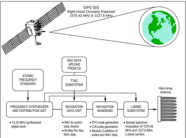
The SPS SIS generation and transmission process for a Block IIA satellite is illustrated in Figure 1.5-1. The Atomic Frequency Standard (AFS) generates a nominal 10.23 MHz clock signal. The signal is distributed by the Frequency Synthesizer and Distribution Unit (FSDU) to other payload subsystems. The Navigation Data Unit (NDU) receives the uploaded navigation (NAV) data from the Control Segment (CS) through the Telemetry, Track, and Command (TT&C) subsystem. The Navigation Baseband generates the pseudorandom noise (PRN) ranging codes and adds the NAV
The SPS is a positioning and timing service provided by way of ranging signals broadcast at the GPS L1 frequency. The L1 frequency, transmitted by all satellites, contains a coarse/acquisition (C/A) code ranging signal, with a navigation data message, that is available for peaceful civil, commercial, and scientific use.
Figure 1.5-1. GPS SIS Generation and Transmission
data message. The L-Band subsystem modulates the binary sequences onto the L1 (1575.42 MHz) and L2 (1227.6 MHz) L-band carriers which are then broadcast by the helix array antenna. Each satellite broadcasts three PRN ranging codes: the precision (P) code, which is the principal ranging code; the Y-code, used in place of the P-code whenever the anti-spoofing mode of operation is activated; and the coarse/acquisition (C/A) code which is used for acquisition of the P (or Y) code (denoted as P(Y)) and as a civil ranging signal. A NAV message based upon data periodically uploaded from the Control Segment is provided by adding the NAV data to both the 1.023 MHz C/A-code sequence and the 10.23 MHz P(Y)-code sequence. The satellite modulates the two resulting code-plus-data sequences onto the L1 carrier, and modulates just the 10.23 MHz code-plus-data sequence onto the L2 carrier; and then both modulated carriers are broadcast to the user community. The entire set of code-plus-data sequences and carriers is referred to as the PPS SIS. A subset of the PPS SIS, the SPS SIS, comprises only the 1.023 MHz code-plus-data sequence on the L1 carrier. Collectively, the PPS SIS and the SPS SIS are known as the satellite's navigation signals (or navigation SIS or GPS SIS).
The satellites are designed to provide reliable service over a 7.5- to 11-year design life, depending on the production block, through a combination of space qualified parts, multiple redundancies for critical subsystems, and internal diagnostic logic. The satellites require minimal interaction with the ground and allow all but a few maintenance activities to be conducted without interruption to the broadcast SIS. Periodic uploads of NAV message data are designed to cause no interruption to the SIS, although Block IIA satellites may experience a 6- to 24-second interruption during the upload.
GPS SIS
Right-Hand Circularly Polarized 1575.42 MHz & 1227.6 MHz ATOMIC FREQUENCY STANDARD NAV DATA UPLOAD FROM CS TT&C SUBSYSTEM FREQUENCY SYNTHESIZER
AND DISTRIBUTION UNIT NAVIGATION BASEBAND
Helix Array Antenna L-BAND SUBSYSTEM NAVIGATION DATA UNIT 10.23 MHz synthesized
digital clock NAV & control data checks 50 Bits Per Sec NAV data
P(Y)-code generation C/A-code generation Modulo-2 addition of codes and NAV data
Spread spectrum modulation of 1575.42 MHz and 1227.6 MHz L-band carriers C/A-code generation Modulo-2 addition of codes and NAV data
1.5.2 GPS Control Segment
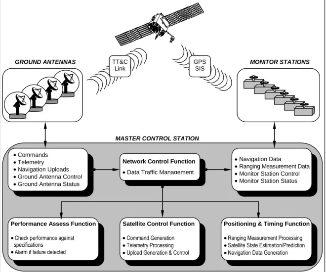
The Operational Control System (OCS) is comprised of four major subsystems: a Master Control Station (MCS, soon to be replaced by a New Master Control Station [NMCS]), a Backup Master Control Station (BMCS, soon to be replaced by an Alternate Master Control Station [AMCS]), a network of four ground antennas (GAs), and a network of globally-distributed monitor stations (MSs). An overview of the OCS is provided in Figure 1.5-2.
Figure 1.5-2. The GPS Operational Control System (OCS)
The MCS is located at Schriever Air Force Base, Colorado, and is the central control node for the GPS satellite constellation. Operations are maintained 24 hours a day, seven days a week throughout the year. The MCS is responsible for all aspects of constellation command and control, to include:
Routine satellite bus and payload status monitoring Satellite maintenance and anomaly resolution Commands
Telemetry
Navigation Uploads Ground Antenna Control Ground Antenna Status
GROUND ANTENNAS TT&C Link
GPS SIS
MONITOR STATIONS
MASTER CONTROL STATION
Navigation Data
Ranging Measurement Data Monitor Station Control Monitor Station Status
Positioning & Timing Function
Ranging Measurement Processing Satellite State Estimation/Prediction Navigation Data Generation
Satellite Control Function
Command Generation Telemetry Processing Upload Generation & Control
Performance Assess Function
Check performance against specifications
Alarm if failure detected
Network Control Function
Management of GPS SIS performance in support of all performance standards (SPS PS and PPS PS)
NAV message data upload operations as required to sustain performance in accordance with accuracy and integrity performance standards
Detecting and responding to GPS SIS failures
In the event of a prolonged MCS outage, GPS operations can be moved to the BMCS (or from the NMCS to the AMCS).
The DoD does not currently monitor and assess SPS performance in real time. The U.S. Government does monitor PPS SIS UREs for all satellites in view of Operational Control Segment (OCS) monitor stations in near-real time, to ensure they are meeting performance objectives. The OCS's four GAs provide a near real-time TT&C interface between the satellites and the MCS. The MSs provide near real-time satellite pseudorange measurement data and recovered NAV message data to the MCS and support continuous monitoring of constellation performance. The current OCS monitor stations provide 100% global coverage with the inclusion of National Geospatial-Intelligence Agency (NGA) stations.
The OCS provides the second line of defense against SIS anomalies. The first line of defense against SIS anomalies are the satellites themselves. The satellites automatically remove themselves from service whenever they experience any of a number of different kinds of on-board failures that could result in SIS anomalies. This removal from service is accomplished by the satellite switching from broadcasting its normal navigation signals to instead broadcasting signals with non-standard PRN code sequences and/or default NAV message data. When a failure occurs that is not covered by the automatic removal capability, the OCS will respond to the failure by manually removing the satellite from service in a prompt manner, subject to MS visibility, GA visibility, and OCS equipment and communications reliability constraints. For details on both automatic and manual removal from service, see the SPS SIS integrity alarms listed in paragraph 2.3.4 and the related SPS SIS integrity performance standards given in Section 3.5 and discussed in Section A.5.
When a MS is tracking a satellite's GPS SIS and the MCS is receiving the L-band measurements in near-real time, the MCS monitors the following GPS SIS metrics (among others) from that satellite:
a. pseudorange error, and
b. pseudorange rate error (i.e., the first time derivative of the pseudorange error, also known as the pseudorange "velocity" error).
The MCS does not directly monitor the pseudorange acceleration error (i.e., the second time derivative of the pseudorange error, also known as the pseudorange rate rate error).
The pseudorange error and the pseudorange rate error for each GPS SIS are used internally by the MCS to determine how to manage each satellite to ensure its GPS SIS meets the performance standards (particularly the integrity standards). There are three primary options: (1) if the satellite's pseudorange error is small enough and growing slowly enough, then no action needs to be taken until the next regularly scheduled upload of NAV message data to that satellite; (2) if the satellite's pseudorange error is large enough or is growing quickly enough, then an unscheduled contingency upload may be performed to refresh the satellite's NAV message data and restore the accuracy/integrity of the GPS SIS; or (3) in extreme cases, if the satellite's pseudorange error is very large or is growing so rapidly that the satellite is at risk of exceeding its integrity tolerance, then the MCS may need to manually remove the satellite from service.
SECTION 2.0 SPS SIS Characteristics and
Minimum Usage Assumptions
This section provides an overview of the SPS SIS interface characteristics, SPS SIS performance characteristics, and the assumptions made to arrive at the performance standards in Section 3.0. The representative receiver characteristics are used to provide a framework for defining the SPS performance standards. They are not intended to impose any minimum requirements on receiver manufacturers or integrators, although they are necessary attributes to achieve the SPS performance described in this document. Receiver characteristics used in this standard are required in order to establish a frame of reference in which the SPS SIS performance can be described.
2.1 SPS SIS Interface Specification (IS) Requirements
The SPS SIS shall comply with the technical requirements related to the interface between the Space Segment and the SPS receivers as established by the current revision of IS-GPS-200. In the event of conflict between the SPS SIS interface characteristics described in this document and the IS, defer to the IS.
2.2 Overview of SPS SIS Interface Characteristics
This section provides an overview of the SPS SIS interface characteristics. SPS SIS interface characteristics are allocated to two categories: (1) carrier and modulation radio frequency (RF) characteristics, and (2) the structure, protocols, and contents of the NAV message.
2.2.1 SPS SIS RF Characteristics
The satellites transmit right-hand circularly polarized (RHCP) L-band signals at the frequency known as L1 at 1575.42 MHz as specified in IS-GPS-200. This signal is transmitted with enough power to ensure the minimum signal power levels of -158.5 dBW for L1 C/A-code under the conditions defined in IS-GPS-200.
L1 consists of two carrier components which are in phase quadrature with each other. Each carrier component is bi-phase shift key (BPSK) modulated by a separate bit train. One bit train is the Modulo-2 sum of the P(Y)-code and NAV data, while the other is the Modulo-2 sum of the C/A-code and the NAV data. For a particular Space Vehicle (SV), all transmitted signal elements (carriers, codes and data) are coherently derived from the same on-board frequency source. See IS-GPS-200 for the definition of the C/A-code.
2.2.2 GPS NAV Message Characteristics
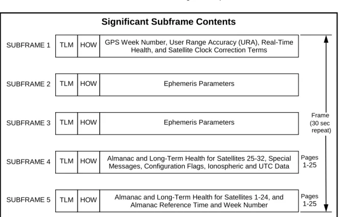
Each satellite broadcasts NAV message data to support the GPS receiver's PVT determination process. Figure 2.2-1 provides an overview of the data contents and structure within the NAV message. It shows each master frame consists of 25 data frames and each data frame consists of 5 subframes. Subframe 4 and 5 data is different (paged) for each data frame within a master frame. Each subframe begins with a telemetry word (TLM) and handover word (HOW) pair. The rest of the data in each subframe includes information required to determine the following:
Satellite time-of-transmission
Satellite position
Satellite (SIS) health
Satellite clock correction
Ionospheric delay effects
Time transfer to Coordinated Universal Time (UTC) as kept by the U.S. Naval Observatory (USNO)
Constellation status
The same NAV message data is broadcast via the SPS SIS and the PPS SIS to all GPS receivers. See IS-GPS-200 for further information on NAV message development.
Figure 2.2-1. NAV Message Content and Format Overview
Significant Subframe Contents
SUBFRAME 1 SUBFRAME 2 Frame SUBFRAME 3 (30 sec repeat) SUBFRAME 4 SUBFRAME 5
TLM HOW GPS Week Number, User Range Accuracy (URA), Real-Time Health, and Satellite Clock Correction Terms
TLM HOW Ephemeris Parameters
TLM HOW Ephemeris Parameters
TLM HOW Almanac and Long-Term Health for Satellites 1-24, and
Almanac Reference Time and Week Number TLM HOW Almanac and Long-Term Health for Satellites 25-32, Special
Messages, Configuration Flags, Ionospheric and UTC Data
Pages
1-25
Pages
2.3 Overview of SPS SIS Performance Characteristics
The SPS SIS performance characteristics are described below. The SPS PS performance characteristics are availability, health, accuracy, integrity, continuity, and UTC(USNO) accuracy.
This overview of the SPS SIS performance characteristics follows a logical progression relative to the output of the SPS SIS from a satellite. Most fundamentally, a satellite’s SPS SIS is considered either trackable or untrackable. A trackable SIS is a SIS which can be preprocessed by an SPS receiver sufficiently to be categorized as either healthy, unhealthy, or marginal. Note that only a trackable and healthy SPS SIS has performance standards for accuracy, integrity, and continuity. The last characteristic in this section relating GPS time to UTC(USNO) applies at the system level and is independent of the output of the SPS SIS from any particular satellite.
2.3.1 SPS SIS Availability
The SPS SIS availability is the probability that the slots in the GPS constellation will be occupied by satellites transmitting a trackable and healthy SPS SIS. For this SPS PS, there are two components of availability as follows:
Per-Slot Availability. The fraction of time that a slot in the GPS constellation will be
occupied by a satellite that is transmitting a trackable and healthy SPS SIS.
Constellation Availability. The fraction of time that a specified number of slots in the
GPS constellation are occupied by satellites that are transmitting a trackable and healthy SPS SIS.
Not all satellites occupy a slot in the GPS constellation. Satellites that are not occupying a slot in the GPS constellation are considered "surplus" satellites. The SPS SIS from a surplus satellite is available if that satellite is transmitting a trackable and healthy SPS SIS. The SPS SISs from surplus satellites always improve the geometric dilution of precision (DOP) provided by the constellation and therefore contribute to accuracy. However, the SPS SISs from surplus satellites do not count towards either the per-slot availability or the constellation availability.
Note:
1. The term "spare satellite" has certain connotations which do not apply to a "surplus satellite." In the past, there were 3 spare satellites in the previous 18+3-satellite and 21+3-satellite constellation baselines. Each of the 3 spare satellites had a pre-defined slot and the operating plan was to launch a new satellite to fill those slots when they were unoccupied. In contrast, the current baseline is a 24-slot constellation, not a 24+3-slot constellation. Surplus satellites do not have pre-defined slots, and there are no a priori plans to replace surplus satellites when they fail. Surplus satellites may be "young" (recently launched) satellites waiting to move into a slot, or they may be "old" (nearly worn out) satellites providing their last few months or years of navigation service before they finally expire.
2.3.2 SPS SIS Health
The SPS SIS health is the status given by the real-time health-related information broadcast by each satellite as an integral part of the SPS SIS. The SPS SIS health is also sometimes referred to as "satellite health" or “space vehicle health” or “SV health”. For this standard, there are three possible SPS SIS health conditions: “healthy”, “marginal”, “unhealthy”. The mapping of the real-time health-related information broadcast by the satellite to these three conditions is given below:
"Healthy". The SPS SIS health is healthy when all of the following four conditions are
(1) There is no SPS SIS alarm indication present. SPS SIS alarm indications are one component of the SPS SIS integrity. The presence of any one of the 9 indications listed in paragraph 2.3.4 means the information provided by the SPS SIS may not be correct.
(2) The SPS SIS indicates the SPS SIS is healthy. More specifically, the six-bit health status word given in subframe 1 of the NAV message is set to all zeros, i.e., binary 0000002 (all NAV data are OK, all signals are OK).
(3) The User Range Accuracy (URA) alert flag is not raised (i.e., bit 18 of the HOW is set to 0). This means the URA is not worse than the URA index value transmitted in subframe 1.
(4) The transmitted SPS URA index in subframe 1 is less than 8 (“N” <8). The URA index is an integer that equates to a range of URA values. A URA index of less than 8 equates to a URA of less than or equal to 48 meters.
The above descriptions only relate to how each condition applies to a healthy SPS SIS. Definitions for all the different settings of conditions 2, 3, and 4 are given in IS-GPS-200.
"Marginal". The SPS SIS health is marginal when the SPS SIS would otherwise have
been defined as healthy except that one or more of the following three warning conditions is or are present:
(1) The SPS SIS indicates that any one of the satellite’s SIS components may not be fully capable. More specifically, the Most Significant Bit (MSB) of the six-bit health status word given in subframe 1 of the NAV message is set to 02 (all NAV data are
OK) and the 5 Least Significant Bits (LSBs) of the six-bit health status word in subframe 1 of the NAV message are set to anything other than 000002 (all signals
are OK), 000102 (all signals dead), or 111002 (SV is temporarily out).
(2) The URA alert flag is raised (i.e., bit 18 of the HOW is set to 1) and the SPS URA does not apply. This means the URA may be worse than the URA index value transmitted in subframe 1 See IS-GPS-200 for details.
(3) The transmitted SPS URA index in subframe 1 is greater than or equal to 8 ("N"=8). A URA index of 8 or greater indicates that the URA is greater than 48 meters or that there is no URA prediction available. See IS-GPS-200 for details.
"Unhealthy". The SPS SIS health is unhealthy when any one or more of the following four
conditions is or are present:
(1) There is an SPS SIS alarm indication present. SPS SIS alarm indications are one component of the SPS SIS integrity. The presence of any one of the 9 indications listed in paragraph 2.3.4 means the information provided by the SPS SIS may not be correct,
(2) The MSB of the six-bit health status word given in subframe 1 of the NAV message is set to 12 (some or all NAV data are bad).
(3) The 5 LSBs of the six-bit health status word in subframe 1 of the NAV message are set to 000102 (all signals dead) or 111002 (SV is temporarily out).
(4) The transmitted SPS SIS is untrackable. Notes:
1. The SPS SIS is unhealthy when the MSB of the six-bit health status word in subframe 1 is set to 12
set to 111112 (more than one combination would be required to describe anomalies). The Control Segment frequently uses this particular combination to indicate a “dead” satellite.
2. Subframes 4 and 5 of the NAV message also contain information related to the SIS health of all satellites in the constellation. This is not real-time information. It is more of a long-term indicator and may not correspond to the actual health of the SIS from the transmitting satellite or from other satellites in the constellation.
3. From the above SIS characteristics, it follows that: (a) a healthy SIS is necessarily trackable, (b) a marginal SIS is necessarily trackable, and (c) an unhealthy SIS may either be trackable or untrackable.
2.3.3 SPS SIS Accuracy
The SPS SIS accuracy is described in two statistical ways; one way is as the 95th percentile (95%) SPS SIS user range error (URE) at a specified age of data (AOD), the other is as the 95% SPS SIS URE over all AODs. With either statistical expression, the SPS SIS accuracy is also known as the SPS SIS pseudorange accuracy. In this context, “pseudorange” means the full pseudorange data set (i.e., the matched combination of a corrected pseudorange measurement and a pseudorange origin, or equivalently the matched combination of a raw pseudorange measurement and the associated NAV data). Other accuracy-related SPS SIS performance parameters include the SPS SIS pseudorange rate (velocity) accuracy defined as the 95% SPS SIS pseudorange rate error over all AODs and the SPS SIS pseudorange acceleration (rate rate) accuracy defined as the 95% SPS SIS pseudorange acceleration error over all AODs.
2.3.4 SPS SIS Integrity
The SPS SIS integrity is defined to be the trust which can be placed in the correctness of the information provided by the SPS SIS. SPS SIS integrity includes the ability of the SPS SIS to provide timely alerts to receivers when the SPS SIS should not be used for positioning or timing. The SPS SIS should not be used when it is providing misleading signal-in-space information (MSI), where the threshold for “misleading” is a not-to-exceed (NTE) tolerance on the SIS URE. For this SPS PS, the four components of integrity are the probability of a major service failure, the time to alert, the SIS URE NTE tolerance, and the alert (either one or the other of two types of alerts).
Probability of a Major Service Failure. The probability of a major service failure for the
SPS SIS is defined to be the probability that the SPS SIS's instantaneous URE exceeds the SIS URE NTE tolerance (i.e., MSI) without a timely alert being issued (i.e., unalerted MSI [UMSI]). Alerts generically include both alarms and warnings.
Time to Alert. The time to alert (TTA) for the SPS SIS is defined to be the time from the
onset of MSI until an alert (alarm or warning) indication arrives at the receiver's antenna. Real-time alert information broadcast as part of the NAV message data is defined to arrive at the receiver’s antenna at the end of the NAV message subframe which contains that particular piece of real-time alert information.
SIS URE NTE Tolerance. The SPS SIS URE NTE tolerance for a healthy SPS SIS is
defined to be 4.42 times the upper bound on the URA value corresponding to the URA index "N" currently broadcast by the satellite. The SIS URE NTE tolerance for a marginal SPS SIS is not defined and there is no SIS URE NTE tolerance for an unhealthy SPS SIS.
Alert – Alarm Indications. An otherwise healthy SPS SIS or marginal SPS SIS becomes
the 9 alarm indications listed below means the information provided by the SPS SIS may not be correct. The SPS SIS alarm indications are defined to include the following:
(1) The SPS SIS becomes untrackable (e.g., ≥ 20 dB decrease in transmitted signal power, ≥ 20 dB increase in correlation loss):
(a) The SPS SIS ceases transmission. (b) The elimination of the standard C/A-code.
(c) The substitution of non-standard C/A-code for the standard C/A-code. (d) The substitution of PRN C/A-code number 37 for the standard C/A-code.
(2) The failure of parity on 5 successive words of NAV data (3 seconds).
(3) The broadcast IODE does not match the 8 LSBs of the broadcast Index of Data Clock (IODC) (excluding normal data set cutovers, see IS-GPS-200).
(4) The transmitted bits in subframe 1, 2, or 3 are all set to 0's or all set to 1's. (5) Default NAV data is being transmitted in subframes 1, 2, or 3 (see IS-GPS-200).
(6) The 8-bit preamble does not equal 100010112, decimal 139, or hexadecimal 8B.
Alert – Warning Indications. An otherwise healthy SPS SIS becomes marginal or
unhealthy when it is the subject of a SPS SIS warning indication. SPS SIS warnings are typically provided in advance of the onset of potential MSI events (i.e., preemptive setting of the six-bit health status word in subframe 1 prior to scheduled maintenance). SPS SIS warnings are also common after an SPS SIS alarm and at satellite end of life. The SPS SIS warning indications are defined in paragraph 2.3.2 above, plus:
(1) An appropriately inflated URA index "N" value (appropriately inflated to cover the expected risk of an abnormally large SPS SIS URE).
Notes:
1. A SPS SIS alarm indication exists when the satellite is not trackable because it is not transmitting the standard C/A-code modulation on the L-band carrier signal. As indicated above, specific SPS SIS alarm indications include the following: (a) when the L-band carrier signal has no modulation (i.e., unmodulated carrier signal), (b) when the L-band carrier signal is modulated by nonstandard C/A-code, and (c) when the L-band carrier signal is modulated by C/A-code number 37. These SPS SIS alarm indications are specifically called out above because of their relatively high probability of occurrence.
2. The SPS SIS alarm indications related to the NAV message data are considered “weak” indications since SPS receivers do not necessarily continuously read each satellite’s NAV message data either by design or by circumstance (e.g., radio-frequency interference [RFI] can prevent reading NAV message data). As a rule of thumb, these weak SPS SIS alarm indications can be assumed to have a five minute lag time before SPS receivers take notice of them for alerting purposes.
3. The SPS SIS alarm indications related to the NAV message data are indicative of a problem onboard the satellite. GPS receivers may perceive similar indications caused by local effects that are unrelated to the broadcast SPS SIS.
4. MSI is the SIS range domain analog of hazardously misleading information (HMI) in the user position domain. SPS SIS MSI may or may not cause some SPS receivers to output HMI.
5. See Appendix A, Section A.5 for additional background information on integrity.
2.3.5 SPS SIS Continuity
The SPS SIS continuity for a healthy SPS SIS is the probability that the SPS SIS will continue to be healthy without unscheduled interruption over a specified time interval. Scheduled interruptions which are announced at least 48 hours in advance do not contribute to a loss of continuity. Scheduled SPS SIS interruptions are announced by way of the Control Segment issuing a "Notice Advisory to Navstar Users" (NANU). NANUs are similar to the "Notices to Airmen" (NOTAMs) issued regarding scheduled interruptions of ground-based air navigation aids. OCS internal procedures are to issue NANUs for scheduled interruptions at least 96 hours in advance.
2.3.6 SPS SIS UTC(USNO) Accuracy
The SPS UTC(USNO) accuracy for a healthy or marginal SPS SIS is defined to be the 95% error in the parameters (ref. 20.3.3.5.2.4 of IS-GPS-200) contained in that SPS SIS which relate GPS time to UTC(USNO).
2.4 Usage Assumptions for SPS Performance Standards
This SPS PS is conditioned upon certain assumptions regarding use of the SPS SIS. Those assumptions are as follows.
2.4.1 SPS User
This SPS PS assumes an SPS user with an SPS receiver.
This SPS PS assumes the GPS receiver complies with the technical requirements related to the interface between the Space Segment and SPS receivers as established by IS-GPS-200.
2.4.2 C/A-Code
This SPS PS assumes the GPS receiver is tracking, processing, and using the C/A-code signals transmitted by the satellites. Pseudorange measurements are assumed to be made by C/A-code tracking with an early-minus-late correlator at 1 chip spacing using an exact replica of the waveform within an ideal sharp-cutoff filter bandwidth at 24 MHz with linear phase centered at the L1 frequency. Carrier phase measurement processing is not assumed.
2.4.3 Single-Frequency Operation
This SPS PS assumes a GPS receiver which only has the hardware capability to track and use the C/A-code signals transmitted by the satellites on L1. The performance standards in Section 3 of this SPS PS are independent of whether the GPS receiver uses the satellite-transmitted ionospheric parameters for single-frequency model-based ionospheric delay compensation purposes or not.
This SPS PS assumes a GPS receiver will apply the single-frequency group delay time correction (TGD) term in accordance with IS-GPS-200.
2.4.4 SPS SIS Health
This SPS PS preferentially uses the term "SPS SIS health" to describe the status indicated by the real-time health-related information broadcast by each satellite as part of the SPS SIS (see paragraph 2.3.2). Occasionally, for consistency with prior usage, this SPS PS may also use the terms "satellite health” or “space vehicle health”.
2.4.4.1 Limitations on SPS SIS Health
This SPS PS assumes a GPS receiver will only consider using a SPS SIS whose health status is indicated as healthy. This SPS PS explicitly assumes a GPS receiver will not use a SPS SIS whose health status is indicated as either marginal or unhealthy.
Notes:
1. It is recognized that GPS receivers may gain operational benefit in certain situations by cautiously
using a SPS SIS whose status is indicated as marginal. Such situations include periods of reduced satellite visibility due to terrain masking, body masking, abnormal receiving antenna orientation, or instances where an additional pseudorange data set is needed for fault exclusion. Although potentially beneficial, use of a SPS SIS whose status is indicated as marginal is not recommended by this SPS PS. If an indicated-as-marginal SPS SIS is used, the reason for the marginal status should be ascertained and the impact on performance (accuracy, integrity, continuity) should be accounted for in that use.
2. It is further recognized that many GPS augmentation systems (e.g., maritime differential GPS
(DGPS) services operating in accordance with the recommendations in RTCM Paper 194-93/SC104-STD, SBAS services operating in accordance with RTCA/DO-229) can override many parts of the real-time and long-term health-related information transmitted by each satellite. If a GPS augmentation system does override any of the health-related information transmitted by the satellites, that GPS augmentation system is explicitly responsible for any and all consequences of the override.
2.4.4.2 Priority of SPS SIS Health Information
This SPS PS assumes a GPS receiver will prioritize the application of the real-time health-related information transmitted by each satellite ahead of the long-term health-related information transmitted by that satellite or any other satellite. The real-time health-related information is as described earlier in paragraph 2.3.2 of this SPS PS. The long-term health-related information is contained in words 3 through 10 of the various pages of subframe 4 and subframe 5 of the NAV data message as shown in Figure 2.2-1 and as further described in IS-GPS-200. In this context, “prioritize” means the GPS receiver will use current real-time health-related information for a GPS SIS whenever it is available in lieu of long-term health-related information for that GPS SIS.
2.4.4.3 Timely Application of SPS SIS Health Information
This SPS PS assumes a GPS receiver will monitor, process, and apply the real-time health-related information transmitted by each satellite (including SPS SIS alert indications) each time the information is transmitted. For real-time health-related information broadcast as part of the NAV message data, the assumed time of application is 2.0 seconds after the end of the NAV message subframe which contains the particular piece of real-time health-related information.
Notes:
1. Real-time alert information broadcast as part of the NAV message data is assumed to require an
additional 2 seconds for application as opposed to real-time alert information not broadcast as part of the NAV message data.
2. As a rule of thumb, the Control Segment will endeavor to operate the SPS SIS in such a manner to
allow GPS receivers at least five minutes to receive, process, and apply the real-time health-related information broadcast as part of the NAV message data before taking any action that could cause a large SPS SIS URE under normal operations and maintenance (O&M) conditions.
It is recognized that GPS receivers cannot always monitor the broadcast NAV message data since interruptions may be caused by temporary signal blockages, abnormal receiving antenna orientation, RFI (particularly jamming), and intermittent environmental effects. Although the GPS receiver is responsible for taking appropriate action when it cannot monitor, process, or apply the current real-time health-related information in the NAV message data, it is possible for the Control Segment to aid some GPS receivers by giving them some advance warning of impending SPS SIS health changes. This action will only be beneficial for SPS SIS integrity if the SPS SIS health changes from healthy to marginal, or from healthy to unhealthy. An example of such an in-advance warning would be setting the 5 LSBs of the six-bit health status word in subframe 1 to 111012 (SV
will be temporarily out) for a period of time before setting the MSB of the six-bit health status word given in subframe 1 of the NAV message to 12 (some or all NAV data are bad) and/or setting the 5
LSBs of the six-bit health status word in subframe 1 to 111002 (SV is temporarily out).
Note:
1. The Control Segment currently provides advance warning of SPS SIS health changes by setting the
MSB of the six-bit health status word in subframe 1 to 12 (some or all NAV data are bad) and setting
the 5 LSBs of the six-bit health status word in subframe 1 to either 111002 (SV is temporarily out) or
111112 (more than one combination would be required to describe anomalies). These are
conservative courses of action. The impact of these courses of action has already been factored into the SPS SIS availability standards.
2.4.5 Excluded Errors
The performance standards in Section 3 of this SPS PS do not take into consideration any error source that is not under direct control of the Space Segment or Control Segment. Specifically excluded errors include those due to the effects of:
Signal distortions caused by ionospheric and/or tropospheric scintillation
Residual receiver ionospheric delay compensation errors
Residual receiver tropospheric delay compensation errors
Receiver noise (including received signal power and interference power) and resolution
Receiver hardware/software faults
Multipath and receiver multipath mitigation
User antenna effects
SECTION 3.0 SPS SIS Performance Standards
This section establishes SPS SIS performance standards for GPS operations. The USAF is committed to operating GPS in accordance with these standards, in a manner consistent with system capabilities and subject to budgetary constraints. The USG reserves the right to adjust GPS constellation management practices as necessary to support military and civil end users. One of the potential adjustments to increase the robustness of constellation availability and enhance the overall SPS SIS performance is an expandable 24-slot constellation consisting of the expansion of three of the baseline 24-slot constellation slots. The USG also reserves the right to optimize performance to support high priority mission needs over an AOO (e.g., maximizing accuracy and availability at the site of a major natural disaster). See the GPS CONOPS for additional details. Any such optimization will not degrade the SPS SIS performance beyond the standards defined in this section for areas outside the AOO.
3.1 Overview
The SPS SIS performance is specified in terms of minimum performance standards for each performance parameter. Each standard includes a definition of conditions and constraints applicable to the provision of the specified service. The phrase “any [healthy] SPS SIS”, when listed as a condition or constraint for any of the performance standards in this section, refers to the individual SPS signal in space transmission from each satellite.
SPS SIS performance standards do not include any element not under the direct control of the GPS Control/Space Segments. Any performance parameters not specified in this section are not considered to be part of the SPS SIS performance standards. Performance parameters not specified in this section or in IS-GPS-200D do not represent a part of the minimum service being provided to the user community.
These SPS SIS performance standards do not directly represent the end performance users will experience. The standards provide a definition of the components of GPS performance that, when combined with a signal reception environment and assumptions concerning the GPS receiver, allow users to define for themselves the end performance they can expect for their particular application. The USG recognizes that these metrics have little direct meaning to the average end user (e.g., pilot, navigator, driver), but they are absolutely essential for GPS receiver designers, system integrators, application engineers, infrastructure and augmentation system developers, space/control segment operators and maintainers, and usage regulators. In support of end users, Appendix B provides an expanded description of the position domain performance implied by the SPS SIS performance standards combined with the typical performance assumptions, including ionosphere, troposphere, and receiver noise error contributions, for a range of GPS receivers to give a sense of the operational characteristics that can be expected under a wide spectrum of operating conditions. Appendix B also gives examples of how to translate the expected pseudorange domain characteristics into end user PVT performance terms.
3.2 24-Slot Constellation Definitions
The GPS baseline 24-slot constellation consists of 24 slots in six orbital planes with four slots per plane. Three of the 24 slots are expandable. The baseline satellites will occupy these slots. Any surplus satellites that exist on orbit will occupy other locations in the orbital planes. There are no a priori specified slots for surplus satellites.
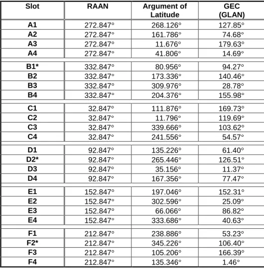
The baseline satellites will be placed in the orbital slots defined by Table 3.2-1 and will be maintained relative to those slots in accordance with the reference orbit specifications and tolerances in Table 3.2-3. Slots for the baseline 24-slot constellation are specified in terms of the Right Ascension of the Ascending Node (RAAN) and the Argument of Latitude for a defined epoch. The corresponding Groundtrack Equatorial Crossing (GEC) values (also known as the Geographic Longitude of the Ascending Node [GLAN] values) are also provided in Table 3.2-1. Tables 3.2-1 and 3.2-3 define the nominal, properly geometrically spaced, baseline 24-slot constellation for GPS.
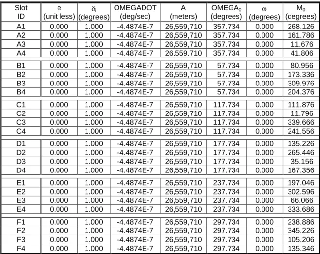
Table 3.2-1. Baseline 24-Slot Constellation Slot Assignments as of the Defined Epoch Slot RAAN Argument of
Latitude GEC (GLAN) A1 272.847 268.126 127.85 A2 272.847 161.786 74.68 A3 272.847 11.676 179.63 A4 272.847 41.806 14.69 B1* 332.847 80.956 94.27 B2 332.847 173.336 140.46 B3 332.847 309.976 28.78 B4 332.847 204.376 155.98 C1 32.847 111.876 169.73 C2 32.847 11.796 119.69 C3 32.847 339.666 103.62 C4 32.847 241.556 54.57 D1 92.847 135.226 61.40 D2* 92.847 265.446 126.51 D3 92.847 35.156 11.37 D4 92.847 167.356 77.47 E1 152.847 197.046 152.31 E2 152.847 302.596 25.09 E3 152.847 66.066 86.82 E4 152.847 333.686 40.63 F1 212.847 238.886 53.23 F2* 212.847 345.226 106.40 F3 212.847 105.206 166.39 F4 212.847 135.346 1.46 Notes:
Epoch: 00:00:00 UTC, 1 July 1993 Greenwich Hour Angle: 18h 36m 14.4s Orbital Slot IDs are Arbitrarily Numbered
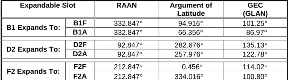
Table 3.2-2. Expandable 24-Slot Constellation Slot Assignments as of the Defined Epoch Expandable Slot RAAN Argument of
Latitude GEC (GLAN) B1 Expands To: B1F 332.847 94.916 101.25 B1A 332.847 66.356 86.97 D2 Expands To: D2F 92.847 282.676 135.13 D2A 92.847 257.976 122.78 F2 Expands To: F2F 212.847 0.456 114.02 F2A 212.847 334.016 100.80
The expandable 24-slot constellation consists of the baseline 24-slot constellation modified to include at least one expandable slot occupied by a pair of satellites in its expanded configuration defined in Table 3.2-2. The fore (F) and aft (A) locations in an expandable slot are defined relative to the baseline slot in the direction of satellite motion. Together, Tables 3.2-1 and 3.2-2 define a total of up to 27 orbital locations and 7 variations of the expandable-24 constellation. There are 3 variations to occupy 25 orbital locations using any 1 expanded slot, 3 variations to occupy 26 orbital locations using any 2 expanded slots, and 1 variation to occupy 27 orbital locations using all 3 expanded slots.
Note that the actual constellation RAAN values will change over each satellite's lifetime due to perturbation forces and variations in each unique orbit's nodal regression rate. The mean nodal regression rate is -0.04187 deg/day for an inclination of 55 . Maintenance of the GEC values and relative spacing of the slots are the controls employed to compensate for orbit plane drift and sustain constellation geometry at acceptable levels. It is also possible for the inclination to drift out of the operational range.
Table 3.2-3. Reference Orbit Parameters
Reference Orbit Parameter Nominal Value Operational Range Required Tolerance
Semi-Major Axis, km Eccentricity
Inclination, deg RAAN, deg
Argument of Perigee, deg
Argument of Latitude at Epoch, deg 26,559.7 0.0 55.0 Note 3 0.0 Note 3 Note 1 0.0 to 0.02 3 180 180 180 Note 2 0.0 to 0.03 N/A N/A N/A Note 1
Note 1: The semi-major axis and orbital period will be adjusted to maintain the relative spacing of the satellite mean arguments of latitude to within 4 deg of the epoch values, with one year or more between orbit adjustments.
Note 2: The nominal value shown provides stationary ground tracks. Note 3: See Tables 3.2-1 and 3.2-2.
3.3 SPS SIS Coverage
This section provides the SPS SIS coverage standards.
There are two components of SPS SIS coverage: (1) the per-satellite coverage, and (2) the baseline/expandable 24-slot constellation coverage. These two components are interrelated. The per-satellite coverage depends primarily on the satellite antenna subsystem design, the on-orbit satellite pointing accuracy, and the satellite altitude (where the allowed range of satellite altitudes is defined by the 24-slot constellation architecture). The baseline/expandable 24-slot constellation coverage depends primarily on the per-satellite coverage coupled with the baseline/expandable 24-slot constellation architecture.
Each component of SPS SIS coverage shall be as specified below.
3.3.1 Per-Satellite Coverage
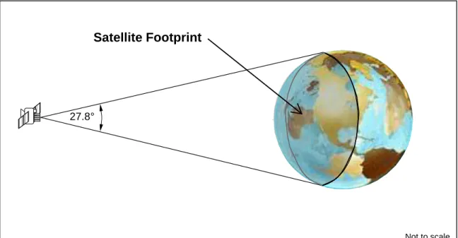
The terrestrial service volume for per-satellite coverage comprises the portion of the near-Earth region which extends from the surface of the Earth up to an altitude of 3,000 km above the surface of the Earth which is visible from the satellite's orbital position (i.e., those portions of the resulting spherical shell surrounding the Earth which are not otherwise physically obscured by the Earth or by localized obstructions). The per-satellite coverage performance standards apply at the worst-case satellite antenna pointing angle relative to the Earth.
The space service volume for per-satellite coverage comprises the near-Earth region which extends from an altitude of 3,000 km above the surface of the Earth up to and including 36,000 km above the Earth’s surface which is visible from the satellite's orbital position. The space service volume coverage is limited by the transmitting satellite’s antenna gain pattern and free-space path loss. The limits of coverage are determined by the received power contour surface of -182 dBW assuming a linear receiving antenna with a minimum gain that varies from +3 dBic at 3,000 km altitude to +7 dBic at 36,000 km altitude. There are no explicit per-satellite coverage standards for the space service volume.
The per-satellite coverage shall be as specified in Table 3.3-1.
Table 3.3-1. SPS SIS Per-Satellite Coverage Standards
SIS Per-Satellite Coverage Standard Conditions and Constraints
Terrestrial Service Volume:
100% Coverage Space Service Volume:
No Coverage Performance Specified
For any healthy or marginal SPS SIS
Note:
1. The guaranteed minimum user-received SPS SIS power levels for the terrestrial service volume are specified in IS-GPS-200. Although IS-GPS-200 uses a 5 degree elevation angle as the reference value for specifying the guaranteed minimum user-received SPS SIS power levels, the per-satellite coverage is not restricted to just those locations where the satellite viewing angle is greater than or equal to 5 degrees above the local horizon. The user-received SPS SIS power levels may be less than the guaranteed minimum at viewing angles below 5 degrees above the local horizon.
3.3.2 Baseline/Expandable Constellation Coverage
The terrestrial service volume for the baseline 24-slot constellation and expandable 24-slot constellation coverage comprises the entire near-Earth region which extends from the surface of the Earth up to an altitude of 3,000 km above the surface of the Earth which is not physically obscured by localized obstructions.
The space service volume for the baseline 24-slot constellation and expandable 24-slot constellation coverage comprises the near-Earth region which extends from an altitude of 3,000 km above the surface of the Earth up to and including 36,000 km above the Earth’s surface. At certain times and locations in the space service volume, the baseline/expandable 24-slot constellations do not provide adequate coverage for instantaneous position solutions. Users operating at those times and locations are therefore limited to time-filtered position solutions propagated over time. There are no explicit constellation coverage standards for the space service volume.
The constellation coverage shall be as specified in Table 3.3-2.
Table 3.3-2. SPS SIS Constellation Coverage Standards
SIS Constellation Coverage Standard Conditions and Constraints
Terrestrial Service Volume:
100% Coverage Space Service Volume:
No Coverage Performance Specified
3.4 SPS SIS Accuracy
This section provides the SPS SIS accuracy standards. The SPS SIS accuracy standards apply to the SIS portion of the GPS error budgets for the user equivalent range error (UERE).
There are four main aspects of SPS SIS accuracy. The standards for each of these aspects are given in this section. The four main aspects are:
1. The pseudorange data set accuracy (i.e., “User Range Error” or URE)
2. The time derivative of the URE (i.e., “User Range Rate Error” or URRE)
3. The second time derivative of URE (i.e., “User Range Acceleration Error” or URAE)
4. The UTC Offset Error (UTCOE)
The standards for each of the four main aspects of SPS SIS accuracy are different depending on the operational application and/or condition of utilization. Refer to Section A.4 in Appendix A for descriptions of the operational applications conditions of utilization. Different SPS SIS accuracy standards are given in this section for:
a. Across all AODs versus at a specified AOD (i.e., either at zero AOD or at maximum AOD) b. Normal operations versus extended operation (see paragraph A.4.3.2)
Regardless of SPS SIS component(s) or operational application/utilization, each of the four main aspects of SPS SIS accuracy are addressed in terms of a "global average" performance standard. In this case, "global average" means root-mean-square (rms) across the portion of the globe in view of the satellite over at least the ergodic period. All of the SPS SIS performance standards in this section are expressed at the 95% probability level in accordance with international standards. The SPS SIS accuracy standards given in the following tables apply to the SPS SIS from all satellites regardless of whether they are occupying locations in the baseline/expandable 24-slot constellation or not. These SPS SIS accuracy standards therefore apply equally to the SPS SIS from baseline/expandable slot satellites and from surplus satellites.
Notes:
1. The accuracy performance standards do not apply beyond the defined bounds of SPS SIS coverage (see Section 3.3).
2. The ergodic period contains the minimum number of samples such that the sample statistic is representative of the population statistic. Under a one-upload-per-day scenario, for example, the traditional approximation for the URE ergodic period is 30 days.
3. Normal operations and extended operations refer to two different GPS operating modes with distinctly different accuracy levels. In the normal operations mode, the satellites are uploaded with fresh NAV message data by the Control Segment on a regular basis. In the extended operations mode, one or more satellites are not uploaded with fresh NAV message data by the Control Segment on a regular basis. See paragraph A.4.3.2 for additional information.
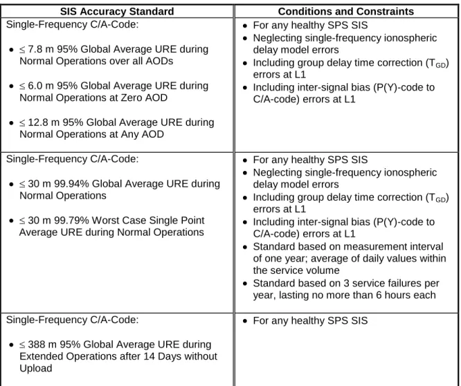
3.4.1 SPS SIS URE Accuracy Standards