PC-CDU
User’s Manual
Reflects PC-CDU Version 2.1.10 MS (Build: April 1, 2002)
Last Updated: August 6, 2002
INTRODUCTION / TERMS AND CONDITIONS
Thank you for purchasing your Topcon receiver. The materials available in this Manual (the "Manual") have been prepared by Topcon Positioning Systems, Inc. (“TPS”) for owners of Topcon products. It is designed to assist owners with the use of PC-CDU software (which may be used with the Topcon receiver) and its use is subject to these terms and conditions (the “Terms and Conditions”).
PLEASE READ THESE TERMS AND CONDITIONS CAREFULLY.
PROFESSIONAL USE. Topcon receivers are designed to be used by a professional. The user is required to be a professional surveyor or have a good knowledge of surveying, in order to understand the user and safety instructions before operating, inspecting or adjusting. Always wear the required protectors (safety shoes, helmet, etc.) when operating the receiver.
COPYRIGHT. All information contained in this Manual is the intellectual property of, and copyrighted mate-rial of TPS. All rights are reserved. One may not use, access, copy, store, display, create derivative works of, sell, modify, publish, distribute, or allow any third party access to, any graphics, content, information or data in this Manual without the express written consent of TPS and may only use such information for the care and operation of your Receiver. The information and data in this Manual are a valuable asset of TPS and are developed by the expenditure of considerable work, time and money, and are the result of original selection, coordination and arrangement of TPS.
TRADEMARKS. Topcon® is a registered trademark of Topcon Corporation. Windows® is a registered trademark of Microsoft Corporation. WinZip® is a registered trademark of Nico Mak Computing, Inc. Prod-uct and company names mentioned herein may be trademarks of their respective owners.
DISCLAIMER OF WARRANTY: EXCEPT FOR ANY WARRANTIES IN A WARRANTY CARD ACCOMPANYING THE RECEIVER, THIS MANUAL AND THE RECEIVER ARE PROVIDED “AS-IS.” THERE ARE NO OTHER WAR-RANTIES. TPS DISCLAIMS ANY IMPLIED WARRANTY OF MERCHANTABILITY OR FITNESS FOR ANY PAR-TICULAR USE OR PURPOSE. TPS AND ITS DISTRIBUTORS SHALL NOT BE LIABLE FOR TECHNICAL OR EDITORIAL ERRORS OR OMISSIONS CONTAINED HEREIN; NOR FOR INCIDENTAL OR CONSEQUENTIAL DAMAGES RESULTING FROM THE FURNISHING, PERFORMANCE OR USE OF THIS MATERIAL, THE SOFT-WARE OR THE RECEIVER. SUCH DISCLAIMED DAMAGES INCLUDE BUT ARE NOT LIMITED TO LOSS OF TIME, LOSS OR DESTRUCTION OF DATA, LOSS OF PROFIT, SAVINGS OR REVENUE, OR LOSS OF THE PRODUCT’S USE. IN ADDITION TPS IS NOT RESPONSIBLE OR LIABLE FOR DAMAGES OR COSTS IN-CURRED IN CONNECTION WITH OBTAINING SUBSTITUTE PRODUCTS OR SOFTWARE, CLAIMS BY OTH-ERS, INCONVENIENCE, OR ANY OTHER COSTS. IN ANY EVENT, TPS SHALL HAVE NO LIABILITY FOR DAMAGES OR OTHERWISE TO YOU OR ANY OTHER PERSON OR ENTITY IN EXCESS OF THE PURCHASE PRICE FOR THE RECEIVER.
LICENSE AGREEMENT.Use of the PC-CDU Software and any other computer programs or software supplied by TPS or downloaded from a TPS website (the “Software”) in connection with a Topcon receiver consti-tutes acceptance of these Terms and Conditions in this Manual and an agreement to abide by these Terms and Conditions. The user is granted a personal, non-exclusive, non-transferable license to use such Soft-ware under the terms stated herein and in any case only with a single receiver or single computer. You may make one (1) backup copy of the Software. Otherwise, the Software may not be copied or repro-duced. You may not assign or transfer the Software or this license without the express written consent of TPS. This license is effective until terminated. You may terminate the license at any time by destroying the Software and Manual. TPS may terminate the license if you fail to comply with any of the Terms or Condi-tions. You agree to destroy the Software and manual upon termination of your use of the receiver. All ownership, copyright and other intellectual property rights in and to the Software belong to TPS. If these li-cense terms are not acceptable, return any unused Software and manual.
CONFIDENTIALITY. This Manual, its contents and the Software (collectively, the “Confidential Informa-tion”) are the confidential and proprietary information of TPS. You agree to treat Confidential Information of TPS with a degree of care no less stringent that the degree of care you would use in safeguarding your own most valuable trade secrets. Nothing in this paragraph shall restrict you from disclosing Confidential Informa-tion to your employees as may be necessary or appropriate to operate or care for the receiver. Such employ-ees must also keep the Confidential Information confidential. In the event you become legally compelled to disclose any of the Confidential Information, you shall give TPS immediate notice so that it may seek a protec-tive order or other appropriate remedy.
WEBSITE; OTHER STATEMENTS. No statement contained at the TPS website (or any other website) or in any other advertisements or TPS literature or made by an employee or independent contractor of TPS modifies these Terms and Conditions (including the Software license, warranty and limitation of liability). SAFETY. Improper use of a Topcon receiver can lead to injury to persons or property and/or malfunction of the product. The receiver should only be repaired by authorized TPS warranty service centers. Users should review and heed the safety warnings in the manual accompanying the receiver.
MISCELLANEOUS. The above Terms and Conditions may be amended, modified, superseded, or canceled, at any time by TPS. The above Terms and Conditions will be governed by, and construed in accordance with, the laws of the State of California, without reference to conflict of laws.
Contents
1. PC-CDU SOFTWARE...1
1.1. PC-CDU’s purposes and functions...1
1.2. Typographic conventions...2
1.3. Terminology and notation...3
1.4. What information can be found in this document? ...4
1.5. System requirements ...4
1.6. Full- and limited-functionality versions of PC-CDU...4
1.7. Technical Support...5
2. SETTING UP PC-CDU ...6
2.1. Installing PC-CDU ...6
2.2. Removing PC-CDU ...8
3. STARTING PC-CDU ...9
3.1. How to start up PC-CDU...9
3.1.1. Direct Mode... 10
3.1.2. ‘Internet Server’ Mode ... 11
3.1.3. ‘Internet Client’ Mode ... 13
3.2. How to close PC-CDU... 14
4. LEARNING PC-CDU IN DETAIL... 16
4.1. Main window... 16
4.1.1. Geo tab... 18
4.1.2. XYZ tab... 20
4.1.3. Target tab ... 20
4.2. The Main window’s menu ... 21
4.2.1. ‘File Manager’ window ... 21
4.2.1.1. Download files... 22
4.2.1.2. The ‘Current log file’ tab... 25
4.2.1.3. ‘Download path’ tab... 27
4.2.2. ‘Real-Time Logging’ dialog window ... 27
4.2.2.1. ‘Single file’ tab... 28
4.2.2.2. ‘Multiple files’ tab... 29
4.2.3. ‘Manual Mode’ window... 33
4.2.4. ‘Receiver Configuration’ window ... 34
4.2.4.1. General... 35 4.2.4.2. MINTER ... 39 4.2.4.3. Positioning ... 42 4.2.4.4. Base... 47 4.2.4.5. Rover ... 50 4.2.4.6. Ports ... 54 4.2.4.7. Events ... 57 4.2.4.8. Advanced... 59
4.2.5. Site Configuration window ... 66
4.2.6. Target Position window ... 66
4.2.7. RFM96 Configuration window ... 67
4.2.8. Initialize file system... 69
4.2.9. Clear NVRAM ... 70
4.2.10. Reset receiver ... 70
4.2.11. Option Manager window... 71
4.2.12. Scatter window... 72
4.2.13. Satellites window ... 74
4.2.14. Position window... 75
4.2.15. Plots Configuration window... 76
APPENDIX A. PC-CDU SCRIPTS... 79
Introduction to PC-CDU scripts ... 79
Variables ... 80
PC-CDU commands... 80
Receiver commands... 82
Running scripts from Windows Explorer... 83
APPENDIX B. OUTPUT PERIOD SETUP WIZARD... 84
List of Figures
Figure 1. Dialog box “Enter Network Password” ...6
Figure 2. Dialog box “File Download”...7
Figure 3. Select a destination for the archive pccdu_ms.zip ...7
Figure 4. Copying data from the website to your computer’s disk drive...8
Figure 5. “Connection Parameters” dialog ... 10
Figure 6. “Connection Parameters” window in Internet Server mode ... 12
Figure 7. “Connection Parameters” window in Internet Client mode ... 14
Figure 8. “Chat” window... 14
Figure 9. Main window ... 16
Figure 10. “Geo” tab ... 18
Figure 11. “XYZ” tab ... 20
Figure 12. “Target” tab ... 20
Figure 13. The Main window’s menu... 21
Figure 14. “Download files” tab... 22
Figure 15. Message notifying that a file with the same name already exists ... 23
Figure 16. Message notifying that a problem occurred while retrieving the current block of data from the receiver... 23
Figure 17. “Current log file” tab... 25
Figure 18. “Site Configuration” dialog box ... 26
Figure 19. “Download path” tab ... 27
Figure 20. “Real-Time Logging” dialog window ... 28
Figure 21. “Multiple files” tab ... 29
Figure 22. Generation of multiple files ... 30
Figure 23. “Overwrite existing files?” warning... 31
Figure 24. “Converter to RINEX Setup” window ... 32
Figure 25. “Manual Mode” window ... 33
Figure 26. “General” tab... 35
Figure 27. “MINTER” tab ... 39
Figure 28. “Positioning” tab ... 42
Figure 29. “<DATUM ID> Datum Parameters” window ... 43
Figure 30. “GPS” tab... 45
Figure 31. “GLONASS” tab ... 45
Figure 32. “WAAS” tab ... 46
Figure 33. “Base” tab ... 47
Figure 34. “Rover” tab... 50
Figure 35. “Ports” tab... 54
Figure 36. “Parallel” subtab ... 56
Figure 37. “Modem” subtab ... 56
Figure 38. “Events” tab ... 57
Figure 39. “Advanced” subtab... 59
Figure 40. “Multipath Reduction” tab ... 60
Figure 41. “Loops Management” subtab... 61
Figure 42. “External Frequency” subtab ... 62
Figure 43. “Raw Data Management” subtab ... 64
Figure 44. “Options” subtab... 66
Figure 45. “Target Position” window... 66
Figure 46. RFM96 item ... 67
Figure 47. “Connect” tab ... 67
Figure 48. Operations the user should take in Power cycle mode ... 68
Figure 49. “Configuration” tab. PDL configuration settings... 68
Figure 50. “Configuration” tab. Recommended settings. ...69
Figure 52. “Reset receiver?” warning ... 70
Figure 53. “Option Manager” window ... 71
Figure 54. “Scatter” window ... 72
Figure 55. “Satellites” window... 74
Figure 56. Pop-up menu, reflecting the information about the selected satellite... 75
Figure 57. “Position” window ... 75
Figure 58. “Plots Configuration” window ... 76
Figure 59. “About PC-CDU” window... 77
Figure 60. Wizard’s 1st window... 84
Figure 61. Wizard’s 2nd window... 85
Figure 62. Wizard’s 3rd window ... 85
Figure 63. Wizard’s 4th window ... 86
List of abbreviations, acronyms and other notation used in
this manual
ARP – Antenna Reference Point
CMR – A format used to transmit differential corrections and related data from the Base receiver to the Rover receiver in DGPS and RTK applications
C/A – Coarse Acquisition code DGPS – Differential GPS DLL – Delay Lock Loop DNS – Domain Name System GUI – Graphical User Interface IP – Internet protocol
LO – Local Oscillator
MINTER – Minimum INTERface. A dedicated user interface designed for TPS receivers NS – Navigation Satellite
P – Precise code
PC – Personal Computer
PLL – (Carrier) Phase Lock Loop
PLLC – (Carrier) Phase Lock Loop Control PS – Pseudorandom Sequence
Receiver – Satellite Navigation User Receiver developed and manufactured by TPS RMS – Root-mean-square
RNSS – Radio Navigational Satellite System
RTCM – (Radio Technical Commission for Maritime Services). This format is used to transmit differential corrections and related data from the Base receiver to the Rover receiver in DGPS and RTK applications
RTK – Real-time kinematic SW – software
1. PC-CDU software
1.1. PC-CDU’s purposes and functions
PC-CDU is a windows application for controlling radio navigation receivers developed and manufac-tured by the Topcon Positioning Systems company.
The most current version of PC-CDU MS (as of 2.1.10, April 1, 2002) provides the following func-tions:
• Connects a PC to a TPS receiver via the computer’s serial or parallel ports (Direct Con-nection Mode).
• Configures a TPS receiver as an “Internet Server”. To do this, the user must run PC-CDU in Internet Server Mode.
• Connects a PC to a TPS receiver that has been configured and is being run in Server Mode via the Internet. In this case the user must run his/her PC-CDU in Internet Client Mode.
• Keeps track of the total number and the status of all visible satellites. • Displays the receiver’s current position and time in real time.
• Controls the recording of raw data measurements into the receiver’s internal memory. • Downloads collected raw data measurements (log files) from the receiver’s internal
memory onto the computer’s disk drives.
• Records, in real time, the receiver’s raw data measurements on the computer’s disk in JPS and RINEX formats (using the executable file jps2rin.exe).
• Displays, in real time, the graph of the receiver’s current position and the satellite sky plot.
• Allows displaying and programming the receiver’s main settings (such as Data Re-cording Interval, Position Computation Mode, etc.).
1.2. Typographic
conventions
Table 1 specifies all typographic conventions used in this manual.
Table 1. Document conventions
Example Description
Clock offset This format is used in definitions or when it is necessary to emphasize that the marked term is technical jargon.
Select from the File… menu Titles of dialog windows/boxes, names of menu options and other GUI components.
Press CTRL+V This format is used to specify keys and key
combinations.
Type the string 194.85.135.59. This format is used to enter various string in-formation (e.g., file and directory names) as well as user commands.
To clear the NVRAM:
1. Select the option Clear NVRAM from the Tools menu…
This format is used to describe the sequence of steps that the user must take.
Note…
The user is recommended to take note of the given information.
Some good hints…
These hints and tips will help the user learn the program faster.
Caution! By no means use…
1.3. Terminology and notation
Table 2 shows what terminology and notation are used for standard Windows GUI components in this manual.
Table 2. Тerms used in this manual to describe standard Windows GUI components
GUI component Term
Button Edit box or indicator
Selected checkbox Unselected checkbox Selected radio button Unselected radio button
Progress bar
Status bar
Spin button
File List box
Drop-down list box
Menu
1.4. What information can be found in this document?
This document provides all information necessary for the user to comprehensively learn PC-CDU be-fore installing and using this software.
In Chapter 2, the reader will find detailed instructions about how to install PC-CDU on a PC. Chapter 3 explains how to launch the program.
Chapter 4, which is intended as a user’s reference manual, focuses on the particular functions this program features.
The appendixes provide supplementary information about PC-CDU:
Appendix A. PC-CDU Scripts introduces readers to the scripts and describes how to use them. Appendix B. Output Period Setup Wizard presents the windows, which are used to adjust the peri-ods of generating raw data and position.
Appendix C. Channel Navigation status codes shows the list of all available satellite navigation status codes.
1.5. System
requirements
Check that you have the following required (or recommended) items before installing and using PC-CDU.
• PC-compatible with Intel® Pentium® 100 MHz or faster. • 5 Мbyte free disk space.
• 16 Мbyte RAM or more (32 Мbyte recommended).
• 32-bit operating system such as MS Windows 95/98/Me/NT/2000. • Color monitor at 640x480 screen resolution.
• Internet Server/Client applications require that your computer has an internet connec-tion.
If run on a Windows NT/2000 computer, PC-CDU does not allow connection to the receiver via the computer’s parallel ports.
1.6. Full- and limited-functionality versions of PC-CDU
PC-CDU exists in two implementations: the full-functionality version called PC-CDU MS, and the reduced-functionality version called PC-CDU Lite. Differences between PC-CDU MS and PC-CDU Lite are listed in Table 3.
Table 3. Differences between PC-CDU MS and PC-CDU Lite
Function PC-CDU MS PC-CDU Lite
Connect to a receiver via the Internet Yes No Record data on a PC’s disk drive in real time
(“Real-Time Data Logging”) Yes No
Graphical presentation of the receiver’s current position &
the satellite sky plot
Yes No
Each version of PC-CDU MS has a limited lifetime as a full-functionality tool. After the current version of PC-CDU MS expires, its extended functions (see Table 2) are automatically disabled so that PC-CDU MS “turns into” PC-CDU Lite.
1.7. Technical
Support
Occasionally, PC-CDU users encounter problems during installation or use of the program. Should you have any problems with PC-CDU, please contact TPS Customer Support. Please be ready to provide TPS Customer Support with the following information:
• Did you try to fix the problem(s) on your own based on the troubleshooting tips avail-able in the manual?
• System/hardware specifications of the computer on which you are running (installing) your PC-CDU.
• ASCII file with a complete list of the receiver options/receiver parameters enabled in your receiver.
For how to obtain a text file listing all receiver options and parameters, please refer to 4.2.16.
To get in contact with TPS Customer Support, please use the following e-mail addresses:
2. Setting up PC-CDU
2.1. Installing PC-CDU
There is no special installer for the current version of PC-CDU. This tool is a ready-to-run executa-ble.
To install PC-CDU on you computer, take the following steps:
1. Visit the TPS section (http://www.topcongps.com/) of the Topcon website page. Click on the Software link in the top-left corner of the window. Next, select the Software
Downloads link. Finally, click on the link Click here to download pccdu_ms.zipto start data downloading.
To download PC-CDU Lite, select the Utilities link on the Software Center page.
2. You will see the dialog box Enter Network Password appears on the screen. You are prompted to enter a username and password. After you type in this information, press OK (Figure 1).
Figure 1. Dialog box “Enter Network Password”
PC-CDU Lite is a freely available software. Thus, when you install PC-CDU Lite, the Enter Network Password prompt will not appear on the screen.
3. The File Download dialog box will be opened. To continue the download process, press Save (Figure 2).
Figure 2. Dialog box “File Download”
4. Use the dialog window Save As to specify the desired destination (disk drive/folder) for the ar-chive pccdu_ms.zip (Figure 3).
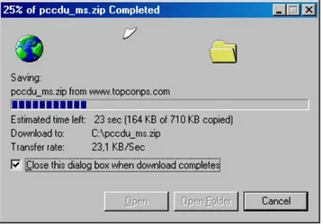
5. Wait while the archive is being downloaded onto your system (Figure 4).
Figure 4. Copying data from the website to your computer’s disk drive. 6. Create a folder on your local disk drive1.
7. Unpack the archive into this folder with WinZip® or another appropriate software.
You will see the following files appear in the folder: • Executable file Pccdu.exe;
• Auxiliary binary file lptaccess.vxd.
2.2. Removing
PC-CDU
The simplest way to remove PC-CDU from a system is to delete the whole directory2 that was
cre-ated when installing PC-CDU and in which Pccdu.exe and other PC-CDU relcre-ated files reside. Also, do not forget to delete the PC-CDU shortcut, if available.
1
It is recommended to use C:\Program Files\TPS\PC-CDU
3. Starting PC-CDU
3.1. How to start up PC-CDU
PC-CDU can be launched, as any other windows program, in one of the following ways: WAY # 1.
Double-click on PC-CDU’s shortcut on the desktop (if it has been created). WAY # 2.
In Windows Explorer go to the directory where Pccdu.exe resides and double-click on the corre-sponding icon.
WAY # 3.
Press the Start button in the bottom-left corner of your computer’s screen and select Run from the pull-up menu. In the Open box specifies the full path to Pccdu.exe. Press OK.
After you first run PC-CDU, you will see the file pccdu.ini appear in the directory from which the executable has been launched. In this .INI file PC-CDU will store all its settings.
If you want to have more than one copy of PC-CDU, each one with its own unique settings, you will need to keep these copies in different directories. Running dif-ferent copies of PC-CDU from difdif-ferent directories will allow you to maintain unique setting for each of the copies.
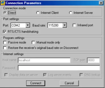
Once PC-CDU is launched, the Connection Parameters window will appear (Figure 5). In this window the user first selects the desired connection mode:
• Direct
• Internet Client • Internet Server
Figure 5. “Connection Parameters” dialog
3.1.1. Direct Mode
This mode is used when it is required to connect a computer and a TPS receiver directly, (i.e., using the computer’s serial or parallel port and an appropriate cable) (see Figure 5).
To connect your computer to the receiver in Direct mode:
1. Select from the Port list box the serial (COM1, COM2, ...) or parallel (LPT1, ...) port that you want to use for the connection.
2. From the Baud Rate list box, select the desired baud rate.
The checkbox Infrared port is selected when you want to use an infra-red adaptor to establish a connection between your computer and receiver over an in-frared data-link.
Connection via an infrared port will be available only if the following conditions are met:
• An appropriate external infrared adaptor is connected to the selected serial port on the computer side.
• Your receiver supports the infrared port hardware-wise. • The Infrared Port option is enabled in your receiver.
3. Select the RTS/CTS handshaking checkbox (optionally).
It is strongly recommended that you select the RTS/CTS checkbox as this makes data exchange between the receiver and computer more reliable.Prior to select-ing this option, make sure that:
• RTS/CTS handshaking is supported both at the computer and at the receiver. • The cable used allows RTS/CTS handshaking.
4. Press Connect.
Along with the above listed options, the user may need to adjust some of the settings in the Program Settings panel. This panel includes the following three options:
• Passive mode • Manual mode only
• Restore the receiver’s original baud rate on Disconnect
In Passive mode PC-CDU is not allowed to change any receiver parameters. Note that in this mode PC-CDU will display in the main window only those satellites whose elevation angles are lar-ger than the elevation mask specified by the parameter Terminal Elevation Mask (see 4.2.4.1). Once Passive mode is off, PC-CDU will automatically force Terminal Elevation Mask to -90º. Therefore the user will be able to view in PC-CDU’s main window (see 4.1) all of the satellites that are being tracked. It is important to remember that this setting (-90º) will be ef-fective as long as the main window remains open. Note however that the original value of Terminal Elevation Mask will not be lost in this case; once the main window is closed, PC-CDU will automatically restore the original mask.
If Manual mode only is on, PC-CDU will perform as an input/output terminal, which allows the user to send commands to and receive information from the receiver.
If the user has selected the checkbox Restore the receiver’s original baud rate on Disconnect, PC-CDU will determine and save the receiver’s original baud rate and then restore this setting automatically on disconnecting the receiver (by pressing the Disconnect menu item).
3.1.2. ‘Internet Server’ Mode
When running PC-CDU in Internet Server mode, the user can configure a TPS receiver3 to
perform as a PC-CDU server. Remote receivers (PC-CDU clients) can then access this PC-CDU-server via the Internet4.
The parameters Port, Baud rate, Infrared port, RTS/CTS handshaking, Passive mode and Manual mode serve the same purposes as in Direct mode (see 3.1.1). The other
3 It is assumed that the receiver is connected to your computer directly.
4 This version allows a TPS receiver configured as PC-CDU-server to be accessed by only one remote
group of parameters, Internet Settings, are intended for the user to tune PC-CDU
for Internet connection: TCP port, Password, Log server events, Display data on server and DNS lookup.
Special attention should be given to setting TCP port for PC-CDU servers5. Make sure that the
selected TCP port does not coincide with any one of the reserved port numbers. The default TCP port number is 8000.
The edit box Password is used to protect the PC-CDU server from unauthorized access. The user can enter in this edit box up to 128 alphanumeric characters.
If the user has selected the checkbox Log server events, there will be created a text log file (pccdu_server.log) in PC-CDU’s working directory. This file will contain all the information that has been collected during the communication session between the PC-CDU server and PC-CDU client. New information will be added to the file after another client connects to the PC-CDU server. If the user wants to view the satellite information and the antenna’s current position in the main windows, he/she must select the Display data on server checkbox. Otherwise no informa-tion will be displayed in the window.
If the checkbox DNS lookup is selected, the file pccdu_server.log will contain the IP and DNS ad-dresses.
Figure 6. shows an example of the Connection Parameters dialog window in Internet Server mode.
Figure 6. “Connection Parameters” window in Internet Server mode
In this example a four-character password and the default TCP port number are used.
5 According to TCP specifications, TCP port number can be up to 64К. Although the user can formally enter a
After the Connect button is pressed, the dialog windows Chat and Main will be
displayed. The Chat window allows an operator running PC-CDU Client to communicate with his/her counterpart who runs the corresponding remote receiver with PC-CDU Server. In addition, this dialog window displays information about the server’s current status.
3.1.3. ‘Internet Client’ Mode
The user selects Internet Client mode when it is required to access a remote receiver that is directly connected with and controlled by a computer on which PC-CDU Server is being run (the obvious pre-condition is that both computers must have access to the Internet.).
After a connection to the remote receiver is established, the user can control this receiver exactly in the same manner as if the user’s computer were directly connected to the receiver, specifically: send commands to the remote receiver, download log files from the receiver’s memory, etc. In or-der to be able to connect to the remote receiver, the user first needs to configure his/her computer as a PC-CDU Client capable of working with the corresponding PC-CDU Server.
The user is required to know the following information about the PC-CDU Server: • IP or DNS address;
• TCP port number; • password (if necessary).
Figure 7. shows an example of the Connection Parameters dialog window with the follow-ing settfollow-ings:
• PC-CDU Server’s IP address: 194.85.135.59; • TCP port number: 8000;
• Password is not used.
In the Host name edit box the user can enter either the server’s IP address (it is 194.85.135.59 in the given example) or its DNS address (it is pab.topconps.com in this case).
Figure 7. “Connection Parameters” window in Internet Client mode
After all necessary settings have been entered into this window, press Connect. You will see PC-CDU open the main window and the Chat window.
The Chat window allows the operator running PC-CDU-Server on one end to exchange messages with the operator running PC-CDU-Client on the other end (Figure 8). Messages sent from the client to the server are preceded by the character “>”. Messages sent by the server to the client begin with the character “<”. The last received message is topmost in the list.
Figure 8. “Chat” window
3.2. How to close PC-CDU
To disconnect from the receiver, select the Disconnect option from the File menu. Alterna-tively, you can use the keys CTRL+D to close the connection.
Pressing the Disconnect button will result in:
• Turning off RTS/CTS handshaking;
• Resetting the receiver parameter /par/out/elm/cur/term to its original value. Only if the checkbox Passive mode has not been deselected;
• Resetting the baud rate to 115200, if the receiver’s original baud rate ex-ceeded 115200;
• Restoring the original baud rate (i.e., that the receiver had before running PC-CDU), only if the option Restore the receiver’s original baud rate on Disconnect has been selected.
To quit PC-CDU, select Exit from the File menu. Alternatively, you can close the program by pressing the keys CTRL+X. If the receiver has not been disconnected by the time the program is terminated, the connection will be automatically broken before PC-CDU is closed.
It is strongly recommended to close the connection with the receiver and close PC-CDU prior to switching the receiver OFF and disconnecting the cable.
4. Learning PC-CDU in detail
4.1. Main window
After PC-CDU has established a connection between the computer and receiver, the main window will be opened (see Figure 9). The main window consists of two panels, the GPS Satellites panel on the left and GLONASS Satellites on the right, which are separated by the Geo|XYZ|Target box. The panels display the basic tracking information (parameters) for the locked satellites. These tracking parameters are described in table 4. The Geo|XYZ|Target box represents the antenna’s current position (if available) and the time-frequency parameters.
Table 4. Tracking parameters displayed in the GPS Satellites and GLONASS Sat-ellites panels
Parameter Description # GPS SV PRN. If the character “*” is shown next to PRN in the column, this means that almanac data are
unavailable for the corresponding satellite.
Sn GLONASS SV Orbital Slot Number. If the character “*” is shown next to Sn in the column, this means that almanac data are unavailable for the corresponding satellite.
Fn GLONASS SV Frequency Number.
EL Elevation angle in degrees. The signs “+” and “-“ immediately following the elevation angles indicate that the corresponding satellites are either ascending and descending, respectively. If a satellite is at maximum elevation, it is marked with “^”.
AZ Azimuth in degrees.
CA Signal-to-noise ratio (C/N0) in the C/A channel [dB*Hz]. P1 Signal-to-noise ratio (C/N0) in the P1 channel [dB*Hz]. P2 Signal-to-noise ratio (C/N0) in the P2 channel [dB*Hz].
TC Time elapsed since the last loss-of-lock in the C/A channel for the corresponding satellite. This time is given in minutes or, if the symbol “:” is specified in the column, in seconds.
SS Satellite navigation status. For a complete description of the satellite navigation status structure, see Appendix C. If a satellite is not used in position computation, its SS flag will be set to “-“. Otherwise “+” will be displayed.
Note that “??” will be displayed anywhere in the panels where the corresponding parameters are unavailable.
The user can sort data in a column in descending (ascending) order by clicking on the column’s ti-tle.
4.1.1. Geo tab
The Geo tab shows the receiver’s antenna’s current position and the time-frequency parameters describing the behavior of the receiver’s local oscillator (Figure 10):
Figure 10. “Geo” tab
• Geodetic coordinates6
- Lat – latitude; - Lon – longitude; - Alt – ellipsoidal height.
• Vel – (magnitude of the) velocity (m/s). • RMS Pos – rms position error7 (m).
• RMS Vel – rms velocity error8 (m/s).
• PDOP – Position dilution of precision. • Solution type:
♦ Standalone ♦ Code differential ♦ RTK float
♦ RTK fixed
• LQ – This field reflects the status of the received differential messages and contains the following information:
♦ Data link quality in percentage.
♦ Time (in seconds) elapsed since the last received message. ♦ Total number of received correct messages.
♦ Total number of received corrupt messages.
6 These geodetic coordinates are computed in WGS 84 regardless of the current value of the
/par/pos/datum/cur parameter. For more details on this parameter, see the GRIL Reference manual.
7 More precisely, this is the square root of the trace of the position error covariance matrix. 8 More precisely, this is the square root of the trace of the velocity error covariance matrix.
If the receiver is not (for some reason) receiving differential corrections or if none of the
ports has been configured to receive differential corrections, the field LQ will either be empty or it will look like this: 100%(999,0000,0000). Currently the values for this field are obtained from the [MS] message.
• Receiver time shows the receiver’s current time within day. This value is taken from the message [~~]. For more information about [~~], see the GRIL Reference Manual.
Currently the message [~~] reports the time within day in the GPS time scale only.
• Receiver date shows the receiver’s current date as specified in the corresponding [RD] message.
• Clock offset describes the time derivative of (Tr – Trr), where Tr designates the
re-ceiver time, Trr designates the receiver reference time. For more information about Tr
and Trr, see the GRIL Reference Manual. This parameter is obtained from the [DO]
message and is expressed in parts per million (ppm).
• Osc. offset is derived from the message [OO] and it is expressed in ppm. The pa-rameter describes the difference between the VCO’s nominal and quiescent frequen-cies.
• Tracking time is the time elapsed since the last complete loss-of-lock event in the receiver’s C/A channels as specified in the corresponding [TT] message.
4.1.2. XYZ tab
The XYZ tab, which is shown in Figure 11, is similar to the Geo tab except for the fact that the position of the receiver’s antenna is displayed in Cartesian coordinates here.
Figure 11. “XYZ” tab
4.1.3. Target tab
The Target tab (Figure 12) is used to display various navigational information, specifically:
Figure 12. “Target” tab
• Lat, Lon –latitude/longitude of the target or of the receiver’s antenna.
• ETT, NTT – ‘Easting-to-target’ and ‘Northing-to-target’ in the local system with the ori-gin at the receiver.
• DTT – ‘Distance-to-target’ (in meters). • CTT – ‘Course-to-target’.
The rest of the parameters have been described above (see the Geo and XYZ tabs).
To set the target coordinates equal to the current receiver coordinates, double-click on either Lat or Lon field.
To reset the timer in the bottom-right corner of the Main Window to 00:00:00, double-click somewhere in the hour:min:second area.
4.2. The Main window’s menu
The user can access any one of PC-CDU’s dialog windows by selecting the corresponding item from the main window’s menu (Figure 13). Some of the menu items have shortcut keys.
For example, the user can select the Site item (from the Configuration menu) with the keys CTRL+I.
Figure 13. The Main window’s menu
The following sections will describe all available menu items and the corresponding dialog windows in detail.
4.2.1. ‘File Manager’ window
To open the File Manager dialog window, select the File Manager item from the File menu, or press the keysCTRL+F.
The File Manager dialog window has three tabs: • Download files
• Current log files • Download path
4.2.1.1. Download files
This dialog window (Figure 14) allows one to delete log files from the receiver memory, or down-load them into a computer.
Figure 14. “Download files” tab
Before downloading the desired log file(s) onto your computer, select the folder on the PC where you want the file(s) to be stored. To do this, use the Download path tab.
Once the destination has been specified, go to the Download files tab, highlight the file(s) that you want to download onto the computer, and press Download.
You will see the following color download status indicators in the course of downloading the data (see Figure 14):
• The green circle ( ) indicates the file(s) that have been successfully downloaded. • The red circle ( ) marks the file that is being downloaded.
• The blue circle ( ) indicates the file(s) in the queue for downloading. The user can interrupt the download by pressing the Stop button.
Files in the destination folder will have the same names and extensions as the original receiver log files. Before downloading the current log file in the destination folder, PC-CDU will check if there al-ready exists a file with the same name in this folder. If such a file is found there, the user will be prompted to select either Append or Overwrite. In the first case the log file downloaded will be appended to the existing file. In the second case the existing file will be overwritten (Figure 15).
Figure 15. Message notifying that a file with the same name already exists
Care should be taken when selecting Append. This option is normally used only if the downloading process has for some reason been interrupted and you want it to be resumed.
The warning ‘Last warning: Waiting for the 1st block’ appearing in the status bar while downloading a log file (Figure 16) indicates that PC-CDU cannot for some reason retrieve the next block of data from the receiver. The field Retries shows how many attempts to retrieve this block of data have been made so far.
Figure 16. Message notifying that a problem occurred while retrieving the current block of data from the receiver
If such a problem occurs, you may need to try a higher baud rate and/or a smaller block size.
Usually, the larger the block size the more efficient the data transfer. On the other hand, if the connection between the computer and receiver is not reliable enough, reducing the block size can often help to exclude or at least minimize communica-tion errors.
Receiver data can also be transferred to the computer via the parallel port, which normally allows a fifteen to twenty-fold reduction in the data transfer time as compared to the serial ports. There are
however three (3) limitations due to which one will not be able to use the parallel ports for data transfer even if such ports are available both in the receiver and the computer.
The first limitation is the requirement that the computer runs under Windows 95, 98 or МЕ. The second limitation is that your computer’s parallel port must be configured as ECP or ECP+EPP. The third limitation is that the option Parallel Port must have been enabled in the receiver.
Selecting the Exclusive mode checkbox will allow one to increase considerably the data trans-fer speed, especially if 115200 or a higher baud rate has been set. Note however that using this op-tion will disable most of the processes running inside the receiver (including the satellite tracking process) in order to ensure the highest possible file transfer speed.
One more note about downloading the receiver log files onto the computer. If the Exclusive mode checkbox is not selected, one can start downloading the current log file without closing it first. The downloading process will stop at the moment when EOF is reached in the log file. However the receiver will continue to write new data to the log file after that.
This method has two drawbacks. First, the download progress indicator can occa-sionally display values exceeding 100%. Second, the last record can be corrupt in the downloaded file. If Exclusive mode is on, it is impossible to start down-loading the current log file without closing it first. In other words, if the Exclusive mode checkbox has been checked and one wants to start down-loading the current log file, PC-CDU will automatically close the log-file after the download is finished.
Use the Delete button to erase unnecessary log-files in the receiver memory.
To delete a group of log files, click on any one of them, then hold down the [CTRL] key and select the rest of the files, and finally press the Delete button.
To delete a group of adjacent log files, click on the first of them, then hold down the [SHIFT] key and click on the last of the files, and finally press the Delete button.
Log files that have inadvertently been deleted from the receiver memory can be restored with the command set,/par/dev/blk/a/removed,on. One can send this com-mand to the receiver from the Manual Mode dialog window. The user is able to recover deleted files only if he/she has not recorded any new files in the re-ceiver memory since these files were removed. Otherwise, it cannot be guaran-teed that the deleted files can be successfully restored.
With the Refresh button the user can reload the list of the receiver log files. Press Exit to close the File Manager tab.
4.2.1.2. The ‘Current log file’ tab
In this tab the user can delete existing and create new receiver log files (Figure 17).
Figure 17. “Current log file” tab
To create (open) a new log file take these steps:
1. Enter the desired filename in the File name edit box, or select a file from the file list displayed in this window. In the latter case, just double-click on the corresponding filename.
2. Specify the desired data recording interval (i.e., “data update interval”) in the Recording interval edit box.
3. Set the desired Elevation mask.
4. Click the Site parameters button. The Site Configuration dialog box will appear (Figure 18). Specify the desired Site Name and then select the correct Antenna Status from the corresponding list box. Set the Antenna Height parameter and select/deselect the Slant checkbox depending on whether you have specified the slant or vertical antenna height. Set the cor-rect Antenna Type. Press OK.
Figure 18. “Site Configuration” dialog box
After the OK button is pressed, the Site parameters dialog box will be closed and the parameters that have been specified in the box will be copied to PCCDU.ini. If one then presses the Start button in the File Manager dialog window, these settings will be enabled and inserted into the newly created (cur-rent) log file.
On the other hand, if one needs to update the site information for the current log file, it will be sufficient to press the Send to receiver button to send the new site settings (site name, antenna status, antenna height, etc.) directly to both the receiver/log-file and PCCDU.ini.
5. Press Start. A new log file will be created9 and the receiver will start recording data into the file.
If you set a recording interval that is not supported by the receiver, PC-CDU will launch a utility calledOutput Period Setup Wizard. For more information on the Wizard, see Appendix B. Output Period Setup Wizard.
To stop data recording and close the file, press the Stop button.
To keep track of the data recording process, see how the log-file size varies in time.
The field Total memory shows the total amount of space in bytes (in the receiver) available for data.
The field Free memory displays how much space in the receiver is free for storing data.
The buttons Delete, Refresh and Exit serve the same purposes as in the Download files tab (see 4.2.1.1).
4.2.1.3. ‘Download path’ tab
In this tab one selects the destination folder for the files downloaded (Figure 19).
Figure 19. “Download path” tab
Note that the window’s right panel is for reference only. One will be prevented from doing any op-erations on the files in the corresponding directory. If the user has not explicitly selected a destina-tion folder for the files downloaded, these files will be stored based on the last specified download path.
4.2.2. ‘Real-Time Logging’ dialog window
The term real-time logging means recording receiver data into a PC in real time mode.
To open the Real-Time Logging dialog window, select Real-Time Logging from the File menu or press the keys CTRL+R.
The Real-Time Logging dialog boxes (see Figure 20 and Figure 21) are, structurally, similar to the Main window. For a description of the GUI components that are identical for the Real-Time Logging and Main windows, refer to 4.1. Below we will focus on the components specific to the Real-Time Logging dialog boxes.
Note the three tabs in the top-left corner of the window: Single file, Multiple files and Select output path. For information on the Select output path tab, refer to 4.2.1.3. Before we getting down to the other two tabs, consider the parameters displayed in the middle of the Real-Time Logging window, between the GPS Satellites and GLONASS Satellites tables.
The Elapsed time field shows the time elapsed since the current log file was opened. Every time a new log file is created, this timer is reset to 00:00:00.
The Received field shows the log-file size in bytes. This parameter will vary as new data are re-corded into the file. After pressing the Stop button, one will see the log-file’s final size in the field.
The Start button allows the user to start recording data into the file. After starting the
data recording the name on the button will change to Stop. Pressing the Stop button will close the file.
If one sets a recording interval that is not supported by the receiver, PC-CDU launches a utility calledOutput Period Setup Wizard. For more informa-tion on the Wizard, see Appendix B. Output Period Setup Wizard.
Press Exit to quit the Real-Time Logging dialog window.
The value of Recording interval specified in the Real-Time Logging win-dow applies only to this mode. The Elevation mask edit box is associated with the receiver parameter /par/out/elm/cur/term.
4.2.2.1. ‘Single file’ tab
Figure 20. “Real-Time Logging” dialog window
In this mode (Figure 20) PC-CDU will record receiver data into one specific file on the host com-puter.
In the Save to edit box enter the name of the file where the receiver data are to be logged.
By default the name of a JPS file created in real-time logging mode will coincide with the site name from the Site Configuration dialog box.
4.2.2.2. ‘Multiple files’ tab
This function, “time logging of multiple log files”, is intended to automate the process of real-time downloading of the receiver data to JPS files according to the specified real-time schedule.
In this mode PC-CDU will automatically open/close JPS files in regular time intervals (Figure 21). A new JPS file will be opened immediately after the previous file is closed.
Figure 21. “Multiple files” tab
The filename convention settings “Prefix” and “Numbering” determine how the JPS files created will be named.
As the name of the setting implies, Prefix determines the prefix part of the filename. By default, PC-CDU will use the site name specified in the Site Configuration dialog window as the file-name prefix.
The Numbering edit box allows you to select the desired file numbering scheme:
• If the option Date & Time is selected, the numeric part of the filename will look as fol-lows: YDDDHHMM,
where
Y – last digit of the year [0-9], DDD – day of the year [1-366],
HH – hours in the receiver time scale [00-23], MM – minutes in the receiver time scale [00-59].
The date and time used for the filename will correspond to the first epoch recorded into the file.
• If the option Ascending Count is selected, the numeric part of the filename will vary be-tween 0000 and 2147483647.
If the option Ascending Count has been chosen, the parameter Start Count will be
enabled. In this edit box one can enter the starting state of the JPS file count, (i.e., the numeric part of the name of the JPS file created first). This count will be incremented as new JPS files are opened.
New file every is associated with a pair of components, an edit box and a drop-down list box. Use the list box to select the desired time unit (day, hour or minute). Use the edit box to specify the interval (in the selected time unit) in which the current JPS file will be closed and the next one will be opened. Note that this interval must be an integer10. Also note that some of the multiple files
created may be shorter (in terms of their duration in time) than it is specified in the corresponding edit box.
To understand better how multiple files are opened and closed in multiple file mode, let’s consider the “artificial” time scale with the origin at 0h00m00s 11) as shown in the figure below. This time
scale is divided into intervals equal to the period as specified by New file every fields.
The first of the multiple JPS files will be opened immediately after the Start button is pressed.
The first file will be closed and the second one opened as the 2nd interval starts, for
example, at t=2n (see the figure below), etc.
Time duration of the second and all the following multiple files (maybe except the last one) will be exactly equal to the selected file period.
To stop the multiple file data logging, press the Stop button. Note that the last file, too, can be shorter than is specified in New file every.
Figure 22. Generation of multiple files
If the user wants PC-CDU to overwrite the existing files whose names coincide with the names of the newly created files, select the Overwrite existing files checkbox before starting real-time logging.
10 Whatever time unit is selected.
Example. Assume that the Ascending Count and Overwrite existing files options have
been selected. If one then presses the Start button, PC-CDU will display a prompt as shown be-low.
Figure 23. “Overwrite existing files?” warning
In this example the destination folder is “E:\c-s-db\ses”, the filename prefix is “Site”. Press Yes (Figure 23) to accept the prompt’s default answer.
If you press No, you will return to the real-time logging window. There you will need first to un-check the Overwrite existing files un-checkbox and then press the Start button to start data log-ging. In this case the numeric parts of the names of the JPS files recorded will be incremented starting from the first unused value, not necessarily from 0000.
If the Autoconvert to RINEX checkbox is selected, PC-CDU will automatically convert all newly created JPS files to RINEX. Note that this conversion is performed “on the move”.
If you want to use the Autoconvert to RINEX function, make sure that the executable file
jps2rin.exe is available on your computer.
The Setup converter button, which is located immediately below the Autoconvert to RINEX checkbox, allows you to set up the jps2rin.exe converter. Pressing this button will open the dialog window Converter to RINEX Setup (Figure 24).
Figure 24. “Converter to RINEX Setup” window
The information specified in the Properties panel will be put in the header of the corresponding RINEX observation file:
• Run by – name of the person or agency launching the jps2rin.exe converter. • Observer – name of the person who collected the data.
• Agency – name of the agency responsible for collecting the data.
• Antenna # - antenna number to be copied in the RINEX observation file. • Antenna type – antenna type to be copied in the RINEX observation file. • Comment – comment line(s).
• Marker name – name of the antenna marker. • Marker number – number of the antenna marker.
In the Application edit box, the full path to jps2rin.exe must be entered. Use the button Browse to select the desired filename path instead of typing it.
Use the checkbox Exclude GPS (Exclude GLONASS) to exclude from the resulting RINEX files all raw data measurements/ephemeris data corresponding to GPS (GLONASS).
Use the checkbox Exclude L1 (Exclude L2) to exclude from the resulting RINEX files all L1 (L2) raw data measurements.
The checkbox Delete source JPS files after successful conversion means exactly what its name implies.
In the Additional options edit box you can enter any of the switches available for the win-dows console application jps2rin.exe. For more information about the switches, refer to the Free Software section at http://www.topcongps.com/software/utilities.html.
In real-time data logging mode it is recommended that the checkbox RTS/CTS
handshaking be selected and the baud rate be set to 115200 or higher.
Unlike downloading the recorded log-files from the receiver memory onto the computer, real-time data logging does not use any error detection/correction pro-tocol in the course of the data transfer. As a result, some of the messages in the created JPS files may be corrupt (due to the serial port overrun or similar problems)12.
4.2.3. ‘Manual Mode’ window
To go to the Manual Mode window, select the Manual Mode item from the File menu or press the keys CTRL+M.
This window (Figure 25) allows direct control of the receiver by using GRIL commands. In manual mode PC-CDU serves as a terminal communicating with the receiver, (i.e., it allows one to send various receiver commands and get responses to these commands). For a complete list of com-mands supported by TPS receivers, refer to the GRIL Reference manual. This document is available for download from the TPS website.
Figure 25. “Manual Mode” window
We recommend that you do not send any commands to the receiver from the
Manual Mode window before you familiarize yourself with the GRIL Reference
manual and acquire good knowledge of the receiver parameters.
At the top of the Manual mode window there is the command line box in which one
can type a (new) command line. Alternatively, one can press to open the combo-box’s list and select one of the previously used command lines. Note that there may be stored up to twenty (20) command lines in the list. Once the desired command line is typed (or selected), press the Send command button in the bottom-left corner of the Manual Mode window or just click the Enter key on your keyboard. The receiver’s responses will be displayed in the receiver replies window located under the command line box.
Use the Stop all messages button to stop outputting any messages to the current terminal13.
With the Clear window button one can clear the receiver replies window. Press Exit to close the Manual Mode window.
The Disconnect button allows the user to disconnect the PC from the receiver. Note however the difference between the Disconnect button you press in the Manual Mode window and the same named item you select from the File menu. If you press Disconnect in the Manual Mode window, PC-CDU will neither automatically disable RTS/CTS handshaking nor restore the re-ceiver port’s original baud rate (regardless of whether the Restore the rere-ceiver’s original baud rate on Disconnect option has been selected).
In other words, if one wants to restore the receiver port’s original baud rate, it can be achieved ei-ther by selecting the Connect item from the File menu or through the Manual Mode win-dow. In the second case, make sure that the command used to change the receiver port’s baud rate is executed immediately before clicking the Disconnect button.
The Start logging button allows the user to copy to a text file all information that has been displayed in the receiver replies window during the session.
With the Load Script button one can load into the receiver the desired script file. Use Edit Script if editing of the script file is needed.
For more information about scripts, see Appendix A. PC-CDU Scripts.
4.2.4. ‘Receiver Configuration’ window
To go to the Receiver Configuration window, select Receiver from the Configuration menu, or alternatively press the keys CTRL+V.
If one selects the Receiver option from the Configuration menu while holding down the Shift key, the Main window will remain open.
You will see a dialog window comprising eight tabs. Each tab has an Apply button. Pressing this button instructs PC-CDU to accept the settings made in the tab without closing the window. Note however that each Apply button serves only “its own” tab and cannot affect the other tabs’ set-tings.
Press Refresh to update the currently displayed window with the new or original set-tings.
The OK button, unlike the individual Apply buttons, allows you to accept the selected settings for all eight tabs at a time. In addition pressing OK will close the Receiver Configuration window.
Use the Exit button to close the Receiver Configuration window without accepting the settings you have made since Apply was pressed last.
Pressing Save will open the Save setup to a script window. In this window you can save the current receiver settings to a script file. Script files normally have the extension .jpc. Later you can load the desired script file to the receiver, thus enabling several necessary receiver settings with a single operation.
The button Set all parameters to defaults does exactly what its name implies.
4.2.4.1. General
Figure 26. shows the Receiver Configuration window’s General tab.
Figure 26. “General” tab
In the Terminal Elevation Mask edit box the user enters the minimum elevation (i.e., the elevation mask angle) for the satellites whose data will be output to the current terminal. This set-ting relates to the receiver parameter /par/out/elm/cur/term.
The radio buttons Internal, External and Auto from the Antenna group are used to select the desired antenna type. These buttons are associated with the receiver parameter /par/ant/inp. Ta-ble 5 shows what antenna type settings are allowed for different receiver models and board types.
Table 5. Allowed antenna type settings
Receiver model Receiver board Default Allowed values
Any JPS_3, Eurocard External Internal, External Any JPS_4, JPS_4_2 External Internal, External,
Auto OEM JGG20 Not available Not available OEM, LEGACY-H HE_GG, HE_GD Not available Not available
HIPER HE_GG, HE_GD Auto Internal, External, Auto OEM, Legacy-E,
ODYSSEY-E E_GGD, HE_GG, HE_GD Not available Not available
Note that such receiver models as HiPer, Regency with JPS_4 board and Odyssey with JPS_4 board are capable of automatically detecting an external antenna only at receiver start-up time. Therefore if one wants to switch from the internal an-tenna to an external one while in auto, he/she will have to power the receiver off and then back on.
The Regency and Odyssey receivers using JPS_4_2 are capable of automatically detecting an external antenna without switching the receiver off and back on. Antenna Status
• The indicator Current Input shows what antenna type is actually being used by the receiver:
int – the internal antenna is being used. ext – an external antenna is being used.
This flag relates to the receiver parameter /par/ant/curinp.
• The indicator Ext. DC Status shows if the external antenna draws any dc: off – the external antenna draws no dc
normal – the external antenna draws normal dc
overload – the external antenna draws higher dc then expected This indicator is associated with the receiver parameter /par/ant/dc.
The indicator Board temperature shows the receiver board’s current temperature. This indi-cator is associated with the receiver parameter /par/dev/thermo/out.
Power management Power
• Use the drop-down list box Power/Mode to select the desired power source for the receiver:
Auto – receiver will automatically select the power source
Mix – receiver will automatically detect and start consuming power from the source with the highest voltage
Battery A – receiver will consume power from battery A Battery B – receiver will consume power from battery B External – an external power supply will be used.
This setting is associated with the receiver parameter /par/pwr/mode.
• The indicator Current Mode shows what power source is being used at the mo-ment. This setting is associated with the receiver parameter /par/pwr/curmode.
Charger
• Use the drop-down list box Charger/Mode to select the battery charging mode: Off – receiver will not charge the batteries
Charge A – receiver will charge only battery A Charge B – receiver will charge only battery B
Auto – receiver will automatically detect and charge the detected batteries. This setting is associated with the receiver parameter /par/pwr/charge/bat.
• Use the Speed list box to set the desired speed of battery charge cycle. You can se-lect between Normal and Fast dc levels. The corresponding receiver parameter is /par/pwr/charge/speed.
• The flag Current Mode shows which of the batteries, a, b or none (off) is being charged at the moment. The corresponding receiver parameter is /par/pwr/charge/curbat. Voltages
• The indicator External shows the external power supply’s voltage. The correspond-ing receiver parameter is /par/pwr/ext.
• The indicator On Board shows what is the actual voltage drawn by the receiver board. The corresponding receiver parameter is /par/pwr/board.
• The indicators Battery A and Battery B show the voltage on batteries A and B, respectively. The corresponding receiver parameters are /par/pwr/bat/a and /par/pwr/bat/b. • The indicator Charger shows the charger’s output voltage during battery charging.
Power output modes
• The checkbox Ports A,B allows you to turn power on and off for ports A and B. The corresponding receiver parameter is /par/pwr/out/ab.
• With the checkbox Port C you can turn power on and off on port C. The correspond-ing receiver parameter is /par/pwr/out/c.
The two above-described parameters are applicable to the Odyssey receiver only. • The list box Ports governs power output on serial ports:
♦ On – the power board will feed all available serial ports via the corresponding pins when the receiver is turned on. If the receiver is turned off, there will not be any power on the ports.
♦ Off – power, for all available serial ports, will be absent even if the receiver is turned on.
♦ Always –all serial ports will be powered even if the receiver is powered off. The Ports list box is associated with the receiver parameter /par/pwr/ports. • With the Slots list box the user governs power output on the internal slots:
♦ On – means that all slots are powered if the receiver is turned on.
♦ Off – means that internal slots will not be powered even if the receiver is turned on.
♦ Always – means that internal slots will be powered even if the receiver is turned off.
The list box is associated with the receiver parameter /par/pwr/slots. Turn on/off Slots
• Select the Slot 2, Slot 3 and Slot 4 checkboxes to enable the corresponding in-ternal slots. These checkboxes correspond to the receiver parameters /par/pwr/switch and /par/pwr/switch/N. The first parameter allows you to enable all slots simultaneously. The second parameter allows you to enable only one slot at a time. Here N is the slot number (2, 3, 4).
The list boxes Ports, Slots and the Turn on/off Slots group box, are applicable to the HiPer and Odyssey-E receivers only.
If the checkbox Enable Low Power Mode is selected, the receiver’s processor will go into low power consumption mode. The corresponding receiver parameter is /par/lpm.
4.2.4.2. MINTER
In this tab (see Figure 27) the user can set up receiver parameters related to MINTER (MINimum INTERface).
Figure 27. “MINTER” tab
The recording time interval specified in the Recording interval edit box will be used when re-ceiver files are opened and logged via MINTER, (i.e., by pressing the FN button). This setting is used not only when logging a single log-file but also when logging receiver data in AFRM mode. The corresponding receiver parameter is /par/log/sc/period. Note that this parameter cannot exceed 86400 seconds.
If an incorrect recording interval is set (the Recording interval edit box), PC-CDU will run a utility called Output Period Setup Wizard. For more in-formation on the Wizard, see Appendix B. Output Period Setup Wizard.
Elevation mask for Log file specifies the minimum elevation angle for the satellites whose data will be put in the receiver files logged via Minter, (i.e., by pressing FN). The corresponding re-ceiver parameter is /par/out/elm/cur/log.
File name prefix specifies what prefix will be added to the names of the receiver files created via Minter, (i.e., by pressing FN). The prefix can be up to 20 characters long. Default is log. The corresponding receiver parameter is /par/cmd/create/prefix.
If the new receiver data are to be appended to an existing log-file, enter the desired filename in the Always append to the file edit box. The setting can be up to twenty characters long. The corresponding receiver parameter is /par/button/file.