KBK 100, I, II-L, II, III crane construction kit
Project drafting and components
202976k0.p65/310505 2
Manufacturer: Demag Cranes & Components GmbH
P.O. box 67 · D-58286 Wetter
Telephone (+49) 2335 92-0 · Telefax (+49) 2335 927676 www.demagcranes.com
Contents
1 Supplementary documents and other publications 52 KBK crane construction kit, general remarks 6
2.1 Introduction 6
2.2 Structure of the KBK crane construction kit 7
2.3 KBK design principles 7
3 Planning and project drafting with KBK 10
3.1 Planning and project drafting KBK suspension crane
and suspension monorail installations 11
3.2 Steps for project drafting and technical specification 12
3.3 Reading off from the diagram 12
3.4 Determining the load GAB on one suspension fitting 13
3.5 System dimensions and system limits 14
3.6 Hoists with KBK 16
3.7 Selection table for KBK monorail tracks 17
3.8 Selection table for KBK single and double-girder cranes 18
3.9 Structural dimensions for monorail tracks and cranes 22
3.10 Project examples 24
4 Basic components for monorail track, crane runway, crane girder 26
4.1 Crane and track elements 26
4.1.1 Straight sections 26
4.1.2 Curved sections 27
4.2 KBK II-T crane girder 28
4.3 Joint bolt set 29
4.4 Internal buffer stop 30
4.5 End cap with buffer 31
4.6 KBK II-R components 32
4.7 Maintenance sections 34
4.8 Information plates 36
5 Assemblies for suspension monorails 37
5.1 Track switch 37
5.1.1 Track switches, dimensions and remarks 37
5.1.2 Integrated busbar line KBK II-R, KBK III-DEL 39
5.1.3 KBK II, II-R, III drive 39
5.1.4 KBK II, II-R, III controls 40
5.2 Turntable 41
5.2.1 Turntables, dimensions and remarks 41
5.2.2 Electrical equipment, KBK II, II-R, III turntables 43
5.3 Drop station 44
5.4 Stop station and separating station 45
5.5 Latching devices for single-girder cranes 46
6 Track suspension 48
6.1 Remarks and overview 48
6.2 Vertical suspension on I-beams 50
6.2.1 I-beam assignment 50
6.2.2 Suspension with suspension rod 50
6.2.3 Coupling for suspension rod 51
6.2.4 Short suspension arrangement with height adjustment 52
6.2.5 Short suspension arrangement without height adjustment 53
6.2.6 KBK II/M10 suspension fitting 53
6.4 Ceiling attachment 55
6.4.1 Suspension with anchor bolt connection 55
6.4.2 U-bolt with upper suspension bracket A 55
6.4.3 Suspension from ceiling section rails with upper suspension bracket A 56
6.4.4 Suspension with floor fixture plate and cover 57
6.4.5 Suspension with upper suspension bracket A and
suspension rods or positive anchors 57
6.5 V-type suspension fitting 58
6.6 Stiffener 59
6.7 Components for V-type suspension / stiffener arrangement 60
6.7.1 V-type upper suspension bracket 60
6.7.2 V-type hinged suspension bracket 61
6.7.3 Spring clip / suspension rod strainer / hinged end piece 62
6.7.4 Packing plate for upper suspension bracket 62
7 Trolleys and trolley combinations 63
7.1 Possible applications 63
7.2 Trolley combinations 64
7.3 Single trolleys 66
7.3.1 Load trolleys 66
7.3.2 Special trolleys for small loads 67
7.3.3 Minimum trolley spacing 67
7.4 Load bar 68
7.5 Load bars for curved travel 69
7.5.1 KBK I load bar 69
7.5.2 Load bar type C 69
7.6 Load bars for travel on straight tracks for trolleys and cranes with a pin 70
7.6.1 Load bar type A 70
7.6.2 KBK II load bar, size 600 70
7.6.3 KBK III load bar 71
7.7 Load bars for travel on straight tracks for trolleys and cranes with two pins 72
7.7.1 Load bar type B 72
7.7.2 KBK III load bar 72
7.8 Crane traverses with rigid crane girder connection 74
7.8.1 Crane end carriage, rigid 74
7.8.2 Crane end carriage, rigid, raised 76
8 Monorail trolley for special hoists 78
8.1 Low-headroom frame for KBK I and KBK II monorail hoists
for straight and curved track 78
8.2 Load bar for DS-1 rope winch and D-SH SpeedHoist 78
8.3 Load bar for D-BP 55 / 110 rope balancer 79
9 Crab 80
9.1 Crab frame 80
9.2 Extending frames 82
9.3 Stacker crabs 84
10 Components for building cranes 86
10.1 Crane suspension eye 86
10.1.1 Crane suspension eye H1, B3 86
10.1.2 HD crane suspension eye KBK II 87
10.2 Spacer bars for crane trolleys 88
202976k0.p65/310505 4
11 Travel drives for crabs and cranes 90
11.1 RF 100 PN friction wheel travel drive 91
11.1.1 Travel drive with disengaging cylinder 91
11.1.2 Travel drive with pressure spring 91
11.1.3 RF 100 PN controls 92
11.2 RF 125 friction wheel travel drive 94
11.2.1 Drive data 94
11.2.2 Control system 94
11.2.3 RF 125 KBK II, II-R, II-L rocker arm 95
11.2.4 Possible arrangements 95
11.3 DRF 200 friction wheel travel drive 96
11.4 Disengaging devices 97
12 Trolleys for travel drives 98
13 Link and spacer bars 99
13.1 Single trolley link 99
13.2 Link bar 99
13.3 Spacer bar with hinged blocks, suitable for curved track 100
13.4 Spacer bar for KBK II-L, II straight track 101
14 Buffers and end stops 102
14.1 KBK I, II-L, II buffer 102
14.2 KBK III buffer 103
15 Fittings 104
15.1 KBK 100, I, II-L, II, III trolley fittings 104
15.2 Rail attachment 105
15.2.1 Bolted bracket 105
15.2.2 Mounting bracket 105
15.3 Mounting plates 106
15.3.1 Mounting plate 1 for switch and magnet fittings 106
15.3.2 Mounting plate 2 for switch and magnet fittings 106
15.3.3 Mounting plate 3 U-plate 107
15.3.4 Mounting plate 4 L-plate 107
16 Power supply to crabs and cranes 108
16.1 Electrical power supply 108
16.1.1 Trailing cable, general information 108
16.1.2 External conductor line 110
16.1.3 Trailing cable, components and attachments 111
16.1.4 KBK II-R integrated conductor line 114
16.1.5 Integrated DEL single-conductor busbar and components for KBK III 115
16.1.6 Mains connection switch/isolating switch 121
16.1.7 Mounting brackets for switches and terminal boxes 122
16.2 Pneumatic power supply 126
16.2.1 General information 126
16.2.2 Components 127
17 KBK standard electrical equipment 130
17.1 General 130
17.2 KBK standard electrical equipment with DC 131
17.3 KBK standard electrical equipment with DK 132
17.4 Schematic illustrations of cable arrangements and cable clamps 134
17.5 KBK standard electrical equipment with DKMES and DKES chain hoists 135
Documentation
Title Part no.
Brochures
KBK crane construction kit 208 385 44
KBK pillar and wall-mounted slewing jib cranes 208 755 44
KBK Aluline crane construction kit 213 051 44
Technical data sheets for KBK installations
KBK installations with KBK 100, I , II (II-L) drop sections 202 772 44
KBK II-R busbar lines, resistance 202 779 44
DKK arrangement on KBK cranes and tracks 202 588 44
Engaging attachment for DKK current collector trolleys on KBK trolleys 202 589 44
KBK 0, 25, 100 trailing cable power supply 202 617 44
Mechanical disengaging device, friction wheel travel drive 202 774 44
KBK II and II-R single-girder crane latching device 202 731 44
Heavy-duty anchor for KBK suspensions and KBK slewing jib cranes 203 276 44
KBK suspensions upper suspension bracket H (profile section rail), upper suspension bracket S, clamp S (large steel profiles),
clamp section V-type suspension arrangement 203 072 44
Trolley pin B6 203 080 44
KBK Aluline 120, 180 203 245 44
KBK ergo 203 309 44
Redundant systems in the KBK crane construction kit 203 334 44
KBK cranes and tracks in explosion hazard areas 203 371 44
DCL arrangement on KBK cranes and tracks 203 510 44
Slewing jib cranes, portal cranes
KBK slewing jib cranes 203 565 44
EVP-KBK single-girder, ZVP-KBK double-girder full portal cranes 202 780 44
Operating instructions, component parts
Suspension monorails and cranes (KBK) 206 076 44
Pillar and wall-mounted slewing jib cranes (KBK) 206 070 44
EVP-KBK single-girder, VP-KBK double-girder full portal cranes 206 213 44
Track switches 214 979 44
Drop sections 206 842 44
Stacker crab 206 846 44
KBK II, II-R latching device 206 850 44
RF disengaging device 206 854 44
KBK Aluline installations classic and ergo 214 173 44
Load bar for D-BP 55 / 110 214 196 44
KBK II extending cranes 214 218 44
KBK ergo operating instructions, component parts 214 475 44
RF 100 travel drive 214 559 44
KBK II-R component parts 222 356 44
Demag chain hoist
Demag DKUN, DKM chain hoists 202 846 44
Demag DC-Pro 1 to DC-Pro 20, DCM-Pro chain hoists 203 525 44
Demag DC-Com 1 to DC-Com 20 chain hoists 203 571 44
Various other data sheets, operating instruction manuals, spare parts lists for electric chain hoist types DK, DC, DS1 (rope winch), DB block winches, DRF friction wheel travel drive units and busbars are also available.
202976k2.p65/310505
General
6
2
KBK crane construction kit, general remarks
2.1
Introduction
The KBK crane construction kit is the efficient and reliable solution for theconstruc-tion of suspension monorails and suspension cranes.
The construction kit consists of standardized mechanical and control components. This facilitates planning, erection and maintenance. KBK installations can be altered and extended at any time. Straight and curved track sections, track switches, turnta-bles and lift and drop sections can be combined to provide the widest range of ma-terials handling solutions.
Installations can range from straight connection between two workplaces with only a few metres of track, to complex monorail networks, and from simple manual control to automatic systems with computer-controlled integration of the various system areas. KBK installations can be easily adapted to new material handlingrequirements. KBK crane installations utilize the free space above working and production areas, thus, valuable floor space is available for materials handling tasks at all times.
Double-girder suspension crane
40470044.eps Single-girder suspension crane
Suspension monorail 41116844.eps 41116744.eps 40780044.eps Turntable Track switch
General
2.2
Structure of the KBK
crane construction kit
2.3
KBK design principles
KBK installations are of modular design. The basic KBK classic construction kit con-sists of simple, well engineered components. Standardized dimensions ensure rapid erection and allow existing installations to be easily modified or extended. All compo-nents are series-produced.
Order-specific special functions can be accommodated with special components and modules by our experienced team of engineers.
The modular construction kit is designed for suspended loads. For
components specially developed to accommodate load moments and forces arising in the opposite direction to the load (kick-up forces), see separate data sheet, ident. no. 203 309 44, KBK ergo.
The KBK Aluline crane construction kit, KBK classic and KBK ergo systems with aluminium profile section rails are referred to in technical data
sheet 203 245 44.
Profile sections
KBK 100 KBK I KBK II-L KBK II KBK II-T KBK III
• Project drafting/engineering based on reliable static analysis
• Series-produced standard components which have been thoroughly tried and tested
• Tailored installations designed for full compliance with safety regulations and standards
• Low-maintenance systems • Simple, fast erection
• Detailed technical documentation
The basic element of the KBK crane construction kit is a cold-rolled special track section in steel with a smooth surfacefinish, high rigidity and low dead weight. Spe-cial guide surfaces and slightly inclined running surfaces guarantee smooth trolley travel. The tracks in the lower and medium SWL range are of inside-running design to protect trolleys and internal (enclosed) busbars. In the upper SWL range and es-pecially in the case of automatic installations, the outside-running design ensures easy accessibility to trolleys and busbars.
42684544.eps
202976k2.p65/310505
General
8
41022545.eps
Trolleys KBK 100, I KBK II-L, II KBK III
41022444.eps 41022344.eps
• Quiet, smooth operation with plastic wheels mounted in anti-friction bearings • Flexible and torque-free load connection via pin
• High vertical load bearing capacity (horizontal up to 10 % of the suspended vertical load)
• Long service life (FEM classification: 3 m) • Horizontally guided in the track profile
• KBK III trolleys can be removed from any point along the track
Trolleys
Track joint All components of each system size (straight and curved sections, track switches,
turntables, etc), have uniform mating dimensions and are easily assembled with bolt-ed connections.
• Positive and non-positive connections
• Adjustable (within the coupling tube/screw tolerance range) • Connections secured against loosening (lock nuts)
• Torque transmission via the track joint
41022044.eps Track joint
Suspension system • Flexible track suspension (minimum lateral forces transmitted to the track system)
• Ball-and-socket universal joint suspension (minimum torque transmission to roof and ceiling superstructures)
• Low-maintenance ball-and-socket joints with plastic sockets • Any angle possible between superstructure and track • Threaded connections for height adjustment
• Spring clip through cross hole locks connection • Slotted holes for height adjustability
• Universal suspension fittings for virtually any superstructure – provided as standard • High suspension load bearing capacities adapted to the track system
• Low headroom possible with short suspension fittings
41022744.eps Suspension system
General
Single-girder and girder designs with rigid crane trolleys or as braced double-girdercranes.
Track switches and turntables for branch sections in monorail tracks. Drop sections and step sections for vertical load movements in the case of trolleys with no hoist unit. Latching devices on cranes for transfer of trolleys from the crane onto monorail and double track systems.
Mechanical safety devices and positive interlocks ensure that the load is secure. Cranes and runways of different section types can be combined (e.g. KBK I track with KBK II crane)
Manipulator cranes and trolleys, cranes with a large overhang, extending cranes and trolleys for handling offset loads which transfer kick-up forces to the KBK compo-nents are designed with special parts. See technical data sheet 203 309 44.
Friction wheels with a high friction coeffi-cient ensure the reliable transmission of the drive torque. Used in KBK systems II-L, II, II-T, III with special trolleys. Pressure applied by springs. Low-noise system.
Travel drives
KBK ergo
Combined crane installations Complex components Electric travel cranes Push travel cranes
41022245.eps Push travel
cranes
41022244.eps
No skewing forces and flexibility of ball-and-socket universal joint suspensions. 41022544.eps
• Standard controls for push and electric travel trolleys and cranes with hoists • Special controls
• Automatic controls • Programmable controllers
KBK components are protected against corrosion as standard.
Suspension components are zinc-galvanized, standard series-produced track sec-tions are powder-coated, other components are provided with a painted finish; spe-cial paint finishes are possible.
KBK installations are designed for operation indoors and for temperatures ranging from –20 °C and + 70 °C. Special measures must be implemented in the case of extreme temperatures, outdoor applications and exposure to aggressive atmospheres.
Power supply systems
Environmental conditions Anti-corrosion protection Electrical and control equipment
41021844.eps Integrated busbars
41021944.eps
In KBK 100, I, II-L, II, flat cable power lines run on cable sliders or cable trolleys in the same track section; the KBK 25 system is used with KBK III. Integrated 5-pole busbar for KBK II (KBK II-R), and up to 10 poles for KBK III (DEL). Protected against accidental contact. Current collector trolleys with single (KBK III) and double pantograph arms (KBK II, III).
202976k3.p65/310505
Planning
10
3
Planning and project drafting with KBK
Regulations KBK installations are dimensioned on the basis of standards DIN 15018
Cranes, DIN 4132 Crane runways and DIN 18800 Part 1, Steel structures. Relevant industrial safety regulations and codes of practice as stipulated in BGV D6 must be observed for planning, project drafting and operating KBK installations. KBK cranes and suspension monorails designed in accordance with the project drafting instructions contained on the following pages with relevant codes of practice concerning the safeguarding of machinery and prevention of accidents, including German technical equipment legislation, accident prevention (UVV) and DIN VDE regulations, and machinery directive 98/37/EC. Manufacturer’s and conformity declarations and KBK test and in-spection booklets for suspension monorails and cranes as well as for pillar and wall-mounted slewing jib cranes are supplied. Instructions in the operat-ing and assembly manuals must be complied with.
Only genuine Demag parts may be used for KBK installations. These parts guarantee the safety of your crane installations. Unauthorised modifications, incorrect usage and incorrect installation exempt the manufacturer from liabil-ity for any damages resulting therefrom.
KBK suspension monorails and KBK suspension cranes require little maintenance. However, 1-2 months after commissioning of an installation, all bolted connections and pin connections should be checked and retightened or secured as necessary. This check should be repeated at least once a year.
Also see KBK suspension crane and monorail operating instructions 206 076 44.
It is important that all members of staff responsible for erection, operation, operational reliability and servicing of KBK installations receive the KBK operating instructions and any relevant literature.
All information and data necessary for project drafting can be found in summary form on the Guidelines for Project Drafting KBK installations sheet.
As a basis for planning, a sketch or drawing should be provided showing a
scale representation of the track system, position of the suspensions and joints and the number of carriers or cranes, branch sections etc.
Planning and project drafting Inspection
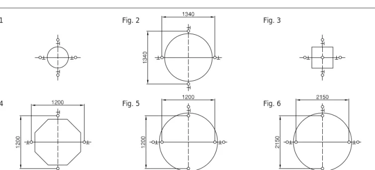
42620544.eps Symbols for use in drawings
Suspension fitting V-type suspension Stiffener Track switch Turntable Latching device Travel drive Straight track section
Curved track section Track joint Buffer End buffers
Collector trolley maintenance section Direction of travel Type Drive Type Trolley Monorail hoist Crab Bracing frame Power feed Power supply line Current collector
Planning
3.1
Planning and project
drafting KBK
suspension crane and
suspension monorail
installations
The diagram below provides the basis for determining the sections for cranes
and tracks, the span lKr and the spacing between the supports lw.
The span and spacing between supports which are permissible for the individual crane and track sections can be read off for a given load. Ensure compliance with the permissible length of overhang, distances of joints from suspension assemblies, and maximum loads on suspension assemblies and trolleys.
Selection of the section sizes KBK 100, KBK I, KBK II-L, KBK II, KBK II-T or KBK III depends on the following factors:
Load K; distance between supports lw or crane span lKr; drive type
all profile section sizes
Diagram for crane and track selection
Diagram: Spacing between supports, crane spans
(Curves apply if hoists are used with lifting speeds up to 15m/min. For higher speeds, see notes on section 3.6 Hoists on KBK.)
42620645.eps
Section inertia moments
KBK 100: 26 cm4
KBK I: 80 cm4
KBK II-L: 345 cm4
KBK II: 660 cm4
KBK III: 1,785 cm4
Neutral axis approx.: KBK 100: 35 mm from lower edge
KBK I, II-L, II, III: section centre
Attention: - - - Limit curves for maximum length of straight sections. Pay attention to the distance between supports and distances of joints (see section 3.4).
The lifted load coefficient ψ, dead weight coefficient ϕ to DIN 15 018 and the oscillation
coefficient ϕ to DIN 4132 for crane groups H1, B3 and the dead weight of each loaded girder have been included in the diagram calculations.
K = Loaded section lw = Distance between supports lKr = Span
(KBK II-T is provided for crane girders only; see crane selection table.)
Selecting the section
Suitable for push travel
Aluline 120
KBK 100 KBK I
Aluline 180
202976k3.p65/310505
Planning
12
3.2
Steps for project
draft-ing and technical
spec-ification
Determining load K lKr and lw
Monorail track and single-girder crane K = GH + G3
Double-girder crane
The girder with the least favourable load (RF friction wheel drive unit) is considered in the following:
K = 0,5 (GH + G3 + GRFK)
Crane runway
Load does not travel on overhung portion of crane girderK = GH + G3 + 0,50 (G)1 + G2)
Load travels on overhung portion of crane girder K = GH + G3 + 0,80 (G)1 + G2)
Crane travels on more than two tracks (centre track) K = GH + G3 + 0,65 (G)1 + G2)
where:
GH = SWL including load handling attachment
G1 = Crane girder dead weight including attachments
G2 = Dead weight of crane trolleys including attachments (both ends together)
G3 = Dead weight of trolley including hoist, cross travel drive and attachments
GRFK = Dead weight of cross travel drive and attachments
A distinction is made between concentrated load, two identical loads or more than two identical loads in one panel.
eKa = Distance between trolleys or wheel axles
eKT = Distance between crane trolleys or wheel axles
For the (concentrated) load K in the panel between supports, the permissible limit for
lw or IKr can be directly read off from the diagram.
42608744.eps Individual load
By adding both loads, a total load Ktot is obtained for which the limits lw(Ktot) or
lKr(KGes) are taken from the diagram. This limit can be increased by applying the
following formula:
max. lw = lw(KGes) + 0,9 . eKa 1) max. lKr = lKr(KGes) + 0,9 . eKa1)
Two identical loads or trolley load bar
42608845.eps
More than two identical loads
42608945.eps
For two or more loads at a maintained distance in one panel, the max. Iw or lKr
must not be greater than the permissible limit for one of the individual loads.
The minimum distance (eKa, eKT) between loaded trolleys is that defined by
the trolley load bar or crane traverse.
Pay attention to the maximum permissible trolley loads!
1) or eKT K Iw/IKr Iw/IKr eKa K KGes K Iw eKa eKa eKa KGes
3.3
Reading off from the
diagram
Span lKr
Distance between track supports lw
(Monorail track and crane runway)
More than two identical loads at equal distances
Two identical loads or load bar Individual load
The loads in one panel between supports are added up and a total load Ktot is
obtained, for which the limit lw(KGes) is taken from the diagram. This limit can be
increased using the following formula:
Planning
3.4
Determining the
suspension load G
ABTwo loads or groups of loads at a
distance eKT
Two or more loads in one or two panels between supports
Iw GAB Iw eKT KGes Iw GAB Iw KGes GAB Iw Iw KGes Individual load 42609045.eps Several identical loads 42609145.eps
Identical load groups
42609245.eps
eKT = 0,5 . lw: GAB = 0.9 KGes + GB. lw. 1,25
eKT = lw: GAB = 0,7 KGes + GB. lw. 1,25 (Distance between loads =
Spacing of supports)
eKT = 1,5 . lw: GAB = 0,5 KGes + GB. lw. 1,25
The suspension fitting with the worst-case load is considered in the following. The load on one suspension fitting is calculated from K for monorail or suspension crane tracks and from the proportional track girder dead weight.
Proportional track girder dead weight = max. distance between fittings . Track girder
weight/m . 1,25.
GB = Track girder weight/m; lw = max. distance between fittings
GAB = KGes + GB. lw. 1,25
The load on one fitting is determined from the sum total of all concentrated loads in two panels and from the proportional track dead weight. If the load on one suspen-sion fitting determined according to this formula exceeds the admissible limit, one or both of the following actions is required:
• Reduce the spacing between supports by providing additional suspension fittings • Distribute loads by spacing loads at a safe distance
GAB = KGes+ GB. lw. 1,25
Max. permissible load GAB on one suspension fitting
G . x a M AB ] g k [ 0 0 1 K B K KBKI KBKII/M10 KBKII-L KBKII KBKIII KBKIII/M20 0 0 4 750 750 1400 1700 1700 2600 Individual load
202976k3.p65/310505
Planning
14
The stability of the girder must be checked for short tracks and crane girders. (Mul-tiply load on overhang by a factor of 1.2; crane girder forms counter torque). KBK tracks or cranes must not be lifted (e.g. where the load is on the overhang).
Important
If the girder is unstable (lifting of girder and/or suspension fitting), the suspension fitting is subjected to impact loading which causes wear and can lead to premature failure of the connection.
See: Solution with KBK ergo.
The maximum and minimum lengths of overhang for cranes can be found in the crane selection table. They pertain directly to the crane girder length.
The length of overhang u can be increased for
• flat cable supply lines by the length of the accumulated cable trolleys at the end of the track where accumulation takes place,
• unloaded spacer trolleys – by the corresponding overall dimension.
The maximum lengths of overhang u for single-girder cranes can be referred to in the crane selection tables.
The approach dimension lan (load hook centre to girder end) is derived from the
dimensions of the individual components.
A suspension fitting has to be provided in the vicinity of each track joint.
Distance st between track joint and suspension fitting Approach dimension
Track overhang Crane overhang
Permissible distance st of joint from suspension fitting
3.5
System dimensions
and system limits
Overhang lengths KBK100 KBKI KBKII-L KBKII KBKIII g n a h r e v o e l b i s s o p t s e t r o h S [mm] umin 65 70 120 120 155 g n a h r e v o r o f s e u l a v g n i t f a r d t c e j o r P [mm] u 100 200 300 300 200 0 0 1 K B K KBKI KBKII-L KBKII KBKIII e c n a t s i d t s e l l a m S [mm] stmin lw≤ m5 65 70 120 120 155 lw>5m 0,05.lw 0,1.lw e c n a t s i d e l b i s s i m r e p m u m i x a M [mm] stmax 0,1.lw 0,2.lw
Single-girder cranes manufactured from just one rail section without girder joint (exception KBK III : 9 m).
1) The push travel capability of larger cranes is limited.
0 0 1 K B K KBKI KBKII-L KBKII KBKII-T KBKIII , s e n a r c r e d r i g -e l g n i s d e t a l u c i t r A l e v a r t h s u p 1) 1-4m 1-6m 1-8m 1-8m 4-7m , m 8 -1 ) m 2 + 7 ( m 9 , s e n a r c r e d r i g -e l g n i s d i g i R h s u p 1)orelectrictravel -e m 6 -8 , 1 lectirictravel, l e v a r t h s u p m 8 - -, m 8 -2 ) m 2 + 7 ( m 9 d e c a r b , s e n a r c r e d r i g -e l b u o D h s u p 1)orelectrictravel m 5 -3 ) y l n o l e v a r t h s u p ( 3-9m 3-10m 3-12m 4-9m 2-14m s e n a r c r e d r i g -e l b u o d d i g i R , h s u p 1)orelectrictravel - 3-10m 3-12m - 2,35-14m
Planning
In the case of double-girder cranes, the individual girders of which consist of several straight sections due to the length of crane required, the permissible distance of track joint to suspension fitting must be taken into consideration. These cranes must be assembled as indicated in the table below. Double-girder cranes running on more than two tracks should be selected from the diagram. In the case of assembled KBK II-T cranes, only the centre track consists of KBK II-T rails (KBK II outside). Single-girder cranes are constructed without a track joint owing to lateral forces and the buffer joint; KBK III is an exception to this rule.
42624644.eps Double-girder cranes
Double-girder cranes with track joint
Construction of double-girder cranes with assembled girders
1) Also for single-girder cranes with KBK III according to crane selection table.
m n i h t g n e l r e d r i g e n a r C KBKI KBKII-L KBKII KBKII-T KBKIII I TH I 1G I 2G I 3G I 1G I 2G I 3G I 1G I 2G I 3G I 1G I 2G I 3G l rK I 1G I 2G I 3G 7 1 6 - - - -8 2 6 - - - 1 6 1 - - - -9 )1 2 5 2 1 8 - 1 8 - 1 7 1 6,2-8,7 2 7 -0 1 -2 8 - 2 8 -0 , 7 -8 , 5 3 7 -- - - 7,0-9,7 2 8 -1 1 - -2 7 2 -0 , 8 -2 , 6 3 8 -- - - 8,0-10,7 2 7 2 2 1 - -2 8 2 -5 , 8 -6 , 6 3 6 3 - - - 8,5-11,6 2 8 2 3 1 - - - -0 , 8 -0 , 7 4 5 4 6 , 1 1 -0 , 8 3 7 3 4 1 - - - -0 , 9 -3 , 7 4 6 4 6 , 1 1 -0 , 9 3 8 3
Possible combinations of sections
for crane and crane runway Crane
y a w n u R KBK100 KBKI KBKII-L KBKII KBKII-T KBKIII 0 0 1 K B K X X X -I K B K X L -I I K B K X I I K B K X
202976k3.p65/310505
Planning
16
3.6
Hoists with KBK
Use of balancer with KBK
The layout diagrams and tables in KBK documentation are valid for Demag chain hoists with lifting speeds up to max. 15m/min.
The use of other chain hoists may result in an overload of the crane installation at limit speeds. Higher hoist speeds and weights may be considered by means of the following factor using the diagrams:
GHnew= GH. (0,97 + 0,002 . vH)
vH = Hoist speed in m/min
Balancers on KBK:
When using rope balancers with KBK, the following must be taken into consideration:
- Rope balancers operate at higher speeds and have higher acceleration values than chain hoists. This increases the lifted load coefficient. The air cushion re-duces the effect of the high acceleration.
- In load handling applications, smaller deflections and vibrations are often re-quired than in classic crane engineering applications.
Pneumatic rope balancers with lifting speeds up to max. 60m/min can be used if
- at least factor 1,1 is used when calculating the load K by means of the diagrams
⇒ K = GH. 1,1 + G3
(this factor may be increased in order to avoid high deflections and unwanted vibrations)
- the selection table for 80kg is used for the D-BP 55 and the selection table for 160 kg is used for the D-BP 110 (at rated SWL) in a simplified manner.
Higher hoist speeds
KBK single and double-girder cranes, monorail and double-rail trolleys can be easily moved by hand. Trolleys and cranes running on KBK II-L, KBK II, KBK II-T or KBK III rails can also be provided with electric travel motors.
Cranes with a girder length of 6 m or more must be fitted with electric travel motors if long travel is to be possible with the trolley in a position outside the central third of the crane girder length. It is also recommended that crabs and cranes with a load capacity greater than 1000 kg SWL be fitted with electric travel drives.
Travel speeds: 5 to 40 m/min.
Under live loading, the deflection of cranes in accordance with the diagram or se-lection table is always below 1/250 of the span. If the maximum spacing between supports/crane span is selected from the middle load range in the selection dia-gram, the deflection ratio ranges from 1/350 to 1/500. Monorail tracks and crane runways have deflection ratios below 1/350. Deflection can be reduced by using larger KBK profile sections.
Deflection Drives
Planning
Tracks according to DIN 4132: H1; B3
GH = Load on hoist (load including dead load of load handling attachment)
K(1) = Total load (live load + trolley dead weight)
K(2) = Total load with electric drive
eKa = Distance between trolley axle (axle base)
lw = Spacing between supports for one trolley
GAB = Max. suspension load for one trolley
Selection basis: 1 load on the monorail track
In individual cases, exact static analysis calculations may lead to different results. Values relating to higher or multiple loads on one track available on request.
3.7
Selection table for
KBK monorail tracks
1) For travel through track switch eKa = 0,8 m
0 0 1 K B K KBKI KBKII-L KBKII(II-R) KBKIII K )(1 _ _ _ _ K )(2 K )(1 _ _ _ _ K )(2 K )(1 _ _ _ _ K )(2 K )(1 _ _ _ _ K )(2 K )(1 _ _ _ _ K )(2 GH e aK lw G BA e aK lw G BA e aK lw G BA e aK lw G BA e aK lw G BA g k kg m m kg kg m m kg kg m m kg kg m m kg kg m m kg 0 5 75 0,065 3,7 95 75 0,065 5,4 130 75 0,085 8 215 75 0,085 8 260 -- - 105 0,085 8 245 105 0,085 8 290 0 8 105 0,065 3 125 105 0,065 5 145 105 0,085 8 245 105 0,085 8 290 -- - 135 0,085 8 275 135 0,085 8 320 5 2 1 160 0,21 2,4 175 160 0,065 4,1 195 170 0,085 7,2 295 170 0,085 8 355 -- - 200 0,085 7 320 200 0,085 8 365 0 6 1 205 0,21 1,85 215 205 0,065 3,4 235 205 0,085 7 320 205 0,085 8 390 -- - 235 0,085 6,5 340 235 0,085 8 420 0 0 2 - 245 0,065 2,95 270 245 0,085 6,4 350 245 0,085 8 430 -- 275 0,085 6 380 275 0,085 8 460 0 5 2 - 300 0,065 2,5 320 305 0,085 5,8 405 305 0,085 8 465 320 0,095 8 620 - 335 0,085 5,55 430 335 0,085 7,5 495 360 0,095 8 660 5 1 3 - 370 0,385 2,2 390 370 0,085 5,15 455 370 0,085 7 530 385 0,095 8 685 - 400 0,085 4,8 480 400 0,085 7 560 425 0,095 8 725 0 0 4 - 455 0,385 1,8 470 455 0,085 4,35 520 455 0,085 6,7 610 470 0,095 8 770 - 485 0,085 4,1 555 485 0,085 6,25 625 510 0,095 8 810 0 0 5 - 590 0,385 1,6 605 590 0,085 3,5 650 590 0,085 5,4 715 600 0,095 8 900 - 620 0,085 3,25 675 620 0,085 5,1 735 640 0,095 8 940 0 3 6 - - 710 0,25 3,15 765 710 0,25 4,7 820 730 0,095 7,7 1020 0 4 7 0,25 3 790 740 0,25 4,6 845 770 0,095 7,4 1050 0 0 8 - - 890 0,25 2,6 935 890 0,25 3,9 980 900 0,095 6,7 1160 0 2 9 0,25 2,5 965 920 0,25 3,8 1010 940 0,095 6,5 1190 0 0 0 1 - - 1090 0,25 2,15 1130 1090 0,25 3,25 1165 1100 0,095 5,7 1320 0 2 1 1 0,25 2,1 1155 1120 0,25 3,2 1195 1140 0,095 5,5 1350 0 5 2 1 - - - 1380 1 3,3 1455 1380 0,500 ) 1 5 1570 0 1 4 1 1 3,3 1485 1420 0,5001) 4,9 1610 0 0 6 1 - - - 1740 1,5 3 1700 1740 0,500 ) 1 4,1 1895 0 7 7 1 1,5 3 1700 1780 0,5001) 4 1930 0 0 0 2 - - - 2140 1,5 1,5 1540 2140 0,500 ) 1 3,4 2270 0 7 1 2 1,5 1,5 1610 2180 0,5001) 3,3 2305 0 0 5 2 - - - - -0 4 7 2 1 2 2550 0 0 2 3 - - - - -0 0 5 3 1,5 1,5 2550
202976k3.p65/310505
Planning
18
lw data apply to one crane on the crane runway.
Crane girder overhangs are always the same on both sides of the crane.
Deflection limits Cranes 1/275, frequency ≥≥≥≥≥ 2,8 Hz
Runways 1/350
lHT= Crane girder length
lKr = Span
lw = Distance between supports
Suspension loads on request All dimensions in m
3.8
Selection table for KBK single and double-girder cranes
Crane girder section, crane girder length
KBK II KBK II-L KBK I KBK 100 Section IHT KBK II KBK II-L KBK I g k 0 0 2 250kg e n a r c r e d r i g -e l g n i S Double-girdercrane Single-girdercrane Double-girdercrane l rK lw l rK lw l rK lw l rK lw I II-L II I II-L II I II-L II I II-L II 1 0,85-0,85 2,7 6,5 8 - - - - 0,85-0,85 2,5 6,1 8 - - - -2 1,8-1,85 2,6 6,4 8 - - - - 1,8-1,85 2,4 6,0 8 - - - -3 2,7-2,85 2,6 6,2 8 2,1-2,85 2,8 6,3 8 2,7-2,85 2,4 5,9 8 2,1-2,85 2,5 5,7 7,9 4 - - - - 2,85-3,85 2,8 6,3 8 - - - - 2,9-3,85 2,4 5,6 7,7 5 - - - - 3,6-4,85 2,6 5,8 8 - - - - 3,7-4,6 2,3 5,5 7,6 6 - - - - 4,3-5,2 2,6 5,8 8 - - - - 4,3-4,7 2,1 5,3 7,3 7 - - - - 5,2-5,2 2,6 5,8 8 - - - -1 0,75-0,75 2,71) 6,1 8 - - - -2 1,7-1,75 2,61) 6,1 8 - - - - 1,7-1,75 2,31) 5,8 8 - - - -3 2,6-2,75 2,51) 5,9 8 1,9-2,75 2,1 4,9 7,2 2,6-2,75 2,31) 5,8 8 2,0-2,75 2,0 4,7 6,9 4 3,3-3,75 2,51) 5,8 8 2,6-3,75 2,0 4,6 6,8 3,4-3,75 2,31) 5,5 8 2,7-3,75 1,9 4,5 6,7 5 4,1-4,75 2,41) 5,7 8 3,3-4,75 2,0 4,6 6,8 4,2-4,75 2,21) 5,35 8 3,4-4,75 1,85 4,3 6,4 6 4,8-5,75 2,31) 5,6 8 3,8-5,75 1,9 4,3 6,3 4,8-5,75 2,11) 5,2 7,8 3,9-5,75 1,8 4,2 6,2 7 5,4-6,75 2,31) 5,5 8 4,3-6,75 1,9 4,3 6,3 5,4-6,1 2,01) 5,0 7,6 4,5-6,75 1,75 4,0 6,0 8 - - - - 6,6-7,75 1,9 4,3 6,3 - - - - 6,6-7,75 1,7 3,9 5,8 9 - - - - 7,8-8,3 1,9 4,3 6,3 - - - - 7,8-8,0 1,7 3,9 5,8 0 1 - - - - 7,0-7,6 1,9 4,3 6,3 - - - - 7,2-7,6 1,7 3,9 5,8 2 1,7-1,75 2,81) 5,9 8 - - - - 1,7-1,75 2,41) 5,8 8 - - - -3 2,5-2,75 2,71) 5,6 8 1,8-2,75 2,0 4,5 6,7 2,5-2,75 2,41) 5,6 8 1,85-2,75 2,03) 4,4 6,5 4 3,2-3,75 2,61) 5,4 8 2,4-3,75 1,9 4,4 6,5 3,2-3,75 2,31) 5,4 8 2,5-3,75 1,93) 4,2 6,2 5 3,9-4,75 2,51) 5,3 8 3,0-4,75 1,8 4,2 6,2 3,9-4,75 2,21) 5,2 8 3,1-4,75 1,83) 4,0 5,9 6 4,5-5,75 2,41) 5,2 8 3,5-5,75 1,8 4,0 5,8 4,5-5,75 2,01) 5,0 7,8 3,65-5,75 1,73) 3,9 5,7 7 5,0-6,75 2,31) 5,0 7,5 4,0-6,75 1,8 3,9 5,7 5,1-6,75 2,01) 4,9 7,5 4,1-6,75 1,73) 3,7 5,5 8 5,7-7,752) 2,01) 4,7 7,0 6,6-7,75 1,8 3,9 5,7 6,0-7,452) 1,61) 4,0 6,0 6,6-7,75 1,73) 3,7 5,3 9 - - - - 7,8-8,75 1,8 3,9 5,7 - - - - 7,8-8,75 1,63) 3,7 5,2 0 1 - - - - 7,0-7,6 1,63) 3,8 5,6 - - - - 7,0-7,6 1,53) 3,6 5,0 1 1 - - - - 8,0-8,8 1,63) 3,8 5,6 - - - - 8,0-8,8 1,53) 3,5 5,0 2 1 - - - - 9,0-10,0 - 3,7 5,5 - - - - 9,0-10,0 - 3,5 5,0 g k 0 5 80kg e n a r c r e d r i g -e l g n i S Double-girdercrane Single-girdercrane Double-girdercrane l rK lw l rK lw l rK lw l rK lw 0 0 1 I II-L II 100 I II-L II 100 I II-L II 100 I II-L II 1 0,85-0,85 3,4 5,5 8 8 - - - 0,85-0,85 3,01) 5,0 8 8 - - - - -2 1,7-1,85 3,3 5,4 8 8 - - - 1,7-1,85 2,91) 5,0 8 8 - - - - -3 2,5-2,85 3,2 5,0 8 8 2,0-2,85 2,9 5,0 7 8 2,6-2,85 2,81) 5,0 8 8 2,0-2,85 2,55 4,7 7 8 4 3,3-3,7 3,1 5,0 8 8 2,6-3,85 2,8 5,0 7 8 - - - 2,7-3,85 2,45 4,5 7 8 5 - - - 3,2-4,85 2,7 5,0 7 8 - - - 3,4-4,2 2,4 4,2 7 8 1 0,8-0,85 3,3 5,4 8 8 - - - 0,85-0,85 2,91) 5,0 8 8 - - - - -2 1,65-1,85 3,2 5,3 8 8 - - - 1,7-1,85 2,81) 5,0 8 8 - - - - -3 2,5-2,85 3,1 5,0 8 8 1,8-2,85 2,6 4,8 7 8 2,5-2,85 2,71) 5,0 8 8 1,9-2,85 2,3 4,2 7 8 4 3,0-3,85 3,0 5,0 8 8 2,3-3,85 2,5 4,6 7 8 3,2-3,85 2,61) 5,0 8 8 2,5-3,85 2,2 4,0 7 8 5 3,6-4,85 2,9 5,0 8 8 3,0-4,85 2,4 4,4 7 8 3,9-4,85 2,51) 4,8 8 8 3,1-4,85 2,1 3,9 7 8 6 4,2-5,4 2,71) 4,5 8 8 4,5-5,85 2,3 4,2 7 8 4,55-4,65 2,41) 4,0 8 8 4,5-5,85 2,0 3,8 7 8 7 - - - 5,6-6,2 2,2 4,0 7 8 - - - 5,6-6,2 1,9 3,6 7 8 8 - - - 5,0-5,1 2,1 3,9 7 8 - - - 5,0-5,1 1,8 3,5 7 8 9 - - - 6,0-6,2 - 3,8 7 8 - - - 6,0-6,2 - 3,4 7 8 1 0,75-0,75 3,0 5,0 8 8 - - - 0,75-0,75 2,81) 4,9 7 8 - - - - -2 1,4-1,75 2,9 5,0 8 8 - - - 1,5-1,75 2,61) 4,7 7 8 - - - - -3 1,95-2,75 2,7 5,0 8 8 1,6-2,75 - 3,2 7,0 8 2,15-2,75 2,51) 4,5 7 8 1,7-2,75 - 3,0 6,6 8 4 2,4-3,75 2,5 4,7 7 8 2,0-3,75 - 3,0 6,6 8 2,7-3,75 2,31) 4,2 7 8 2,2-3,75 - 2,8 6,3 8 5 3,0-4,75 2,4 4,5 7 8 3,0-4,75 - 2,9 6,5 8 3,15-4,75 2,21) 4,0 7 8 3,1-4,75 - 2,7 6,1 8 6 3,5-5,75 2,2 4,3 7 8 3,5-5,75 - 2,8 6,3 8 3,6-5,75 2,11) 3,8 7 8 3,5-5,75 - 2,6 5,9 8 7 4,0-6,75 2,1 4,1 7 8 4,0-6,75 - 2,7 6,1 8 4,0-6,75 1,91) 3,5 7 8 4,0-6,75 - 2,5 5,7 8 8 5,0-7,52) 1,81) 3,51) 7 8 6,6-7,75 - 2,6 6,0 8 5,1-7,42) 1,51) 3,01) 6,5 8 6,6-7,75 - 2,4 5,6 8 9 - - - 7,8-8,75 - 2,6 6,0 8 - - - 7,8-8,75 - 2,3 5,4 7,8 0 1 - - - 7,0-7,6 - 2,5 5,8 8 - - - 7,0-7,6 - 2,2 5,2 7,8 1 0,7-0,75 - 5,0 7 8 - - - 0,75-0,75 - 5,0 7 8 - - - - -2 1,4-1,75 - 5,0 7 8 - - - 1,45-1,75 - 4,7 7 8 - - - - -3 1,8-2,75 - 5,0 7 8 1,5-2,75 - 3,3 6,5 8 2,0-2,75 - 4,5 7 8 1,5-2,75 - 3,0 6,0 8 4 2,2-3,75 - 4,8 7 8 2,0-3,75 - 3,1 6,2 8 2,5-3,75 - 4,2 7 8 2,0-3,75 - 2,7 5,8 8 5 3,0-4,75 - 4,5 7 8 3,0-4,75 - 2,8 6,2 8 3,0-4,75 - 3,8 7 8 3,0-4,75 - 2,6 5,7 8 6 3,5-5,75 - 4,2 7 8 3,5-5,75 - 2,6 5,9 8 3,5-5,75 - 3,6 7 8 3,5-5,75 - 2,4 5,5 8 7 4,0-6,75 - 4,0 7 8 4,0-6,75 - 2,5 5,7 8 4,0-6,75 - 3,5 7 8 4,0-6,75 - 2,3 5,4 7,7 8 5,0-7,752) - 3,41) 7 8 6,6-7,75 - 2,2 5,7 7,7 5,0-7,752) - 3,01) 6,5 8 6,6-7,75 - 2,1 5,4 7,3 9 - - - 7,8-8,75 - 2,1 5,6 7,3 - - - 7,8-8,75 - 2,0 5,3 7,0 0 1 - - - 7,0-7,6 - 2,0 5,4 7,0 - - - 7,0-7,6 - 1,9 5,0 6,7 1 1 - - - 8,0-8,8 - 1,9 5,2 6,7 - - - 8,0-8,8 - 1,8 4,9 6,4 2 1 - - - 9,0-10,0 - - 4,7 6,4 - - - 9,0-10,0 - - 4,5 6,0
Planning
Project drafting data for crane installations must be selected from the table below for KBK single and double-girder cranes. In individual cases, exact static analysis calculations may lead to different results for IKr and Iw.
Where there are several cranes on the same runway, the end carriages of single-girder cranes must al-ways be designed as double or quadruple trolleys.
The spacing of the track supports lw must then be
calculated separately. Intermediate lengths for crane girders are possible. Data calculated on the basis of cranes of standard design for standard components and without special attachments.
Check suspension loads!
Cranes according to DIN 15018, tracks accord-ing to DIN 4132: H1, B3 (H2, B3 on request).
1) Two end carriages on each side of crane 2) Double trolley unit
3) Quadruple trolley end carriages on each side of crane 4) Quadruple trolley unit
KBK II
KBK II-L
KBK I
Crane girder section, crane girder length
KBK II KBK II-L KBK I KBK 100 Section IHT g k 5 2 1 160kg e n a r c r e d r i g -e l g n i S Double-girdercrane Single-girdercrane Double-girdercrane l rK lw l rK lw l rK lw l rK lw 0 0 1 I II-L II 100 I II-L II 100 I II-L II 100 I II-L II 1 0,85-0,852) 2,31) 4,3 7 8 - - - 0,85-0,852) 1,51) 3,2 7 8 - - - - -2 1,8-1,852) 2,31) 4,2 7 8 - - - 1,8-1,852) 1,51) 3,1 7 8 - - - - -3 2,5-2,62) 2,21) 4,2 7 8 2,1-2,85 2,15 3,9 7 8 - - - 2,25-2,85 - 3,4 7 8 4 - - - 2,9-3,6 2,1 3,8 7 8 - - - 3,25-3,3 - 3,3 7 8 5 - - - 3,6-3,6 2,0 3,7 7 8 - - - -1 0,8-0,85 2,31) 4,3 7 8 - - - 0,85-0,85 - 3,3 7 8 - - - - -2 1,75-1,85 2,21) 4,2 7 8 - - - 1,8-1,85 - 3,1 7 8 - - - - -3 2,6-2,85 2,21) 4,1 7 8 2,0-2,85 - 3,6 7 8 2,7-2,85 - 3,0 7 8 2,05-2,85 - 3,1 6,6 8 4 3,4-3,85 2,11) 4,0 7 8 2,7-3,85 - 3,5 7 8 3,5-3,6 - 3,0 7 8 2,8-3,85 - 3,0 6,5 8 5 4,2-4,6 2,01) 3,9 7 8 3,3-4,85 - 3,3 7 8 - - - 3,5-4,85 - 2,9 6,5 8 6 - - - 4,5-5,85 - 3,2 7 8 - - - 4,5-5,85 - 2,9 6,5 8 7 - - - 5,6-6,2 - 3,1 7 8 - - - 5,65-6,1 - 2,9 6,5 8 8 - - - 5,0-5,1 - 3,0 6,7 8 - - - 5,0-5,1 - 2,6 6,0 8 9 - - - 6,0-6,2 - 2,9 6,7 8 - - - 6,0-6,15 - 2,6 6,0 8 1 0,75-0,75 2,01) 3,9 7 8 - - - 0,75-0,75 - 2,8 6,6 8 - - - - -2 1,6-1,75 2,01) 3,9 7 8 - - - 1,7-1,75 - 2,8 6,6 8 - - - - -3 2,4-2,75 2,01) 3,8 7 8 1,8-2,75 - 2,6 6,0 8 2,6-2,75 - 2,8 6,6 8 1,8-2,75 - 2,2 5,2 7,5 4 3,0-3,75 2,01) 3,8 7 8 2,4-3,75 - 2,5 5,7 8 3,3-3,75 - 2,7 6,5 8 2,5-3,75 - 2,1 4,8 7 5 3,6-4,75 2,01) 3,7 7 8 3,1-4,75 - 2,4 5,5 8 4,0-4,75 - 2,6 6,2 8 3,2-4,75 - 2,1 4,8 7 6 4,1-5,75 1,91) 3,6 7 8 3,6-5,75 - 2,3 5,3 7,8 4,6-5,75 - 2,51) 6,0 8 3,7-5,75 - 2,0 4,5 6,6 7 4,5-6,75 1,81) 3,5 6,5 8 4,1-6,75 - 2,2 5,1 7,6 5,0-6,75 - 2,51) 6,0 8 4,2-6,75 - 2,0 4,5 6,6 8 5,6-7,02) - 2,51) 6 7,5 6,6-7,75 - 2,2 5,1 7,6 6,0-6,752) - 2,31) 5,6 7,5 6,6-7,75 - 2,0 4,5 6,6 9 - - - 7,8-8,75 - 2,1 5,0 7,5 - - - 7,8-8,75 - 2,0 4,5 6,6 0 1 - - - 7,0-7,6 - 2,1 5,0 7,5 - - - 7,0-7,6 - 2,0 4,5 6,6 1 0,75-0,75 - 4,1 7 8 - - - 0,75-0,75 - 3,4 6,75 8 - - - - -2 1,6-1,75 - 3,8 7 8 - - - 1,65-1,75 - 3,2 6,5 8 - - - - -3 2,2-2,75 - 3,6 7 8 1,6-2,75 - 2,5 5,4 8 2,45-2,75 - 3,01) 6,1 8 1,8-2,75 - 2,1 4,8 7,2 4 2,8-3,75 - 3,4 7 8 2,2-3,75 - 2,4 5,3 8 3,15-3,75 - 2,81) 5,9 8 2,3-3,75 - 2,0 4,6 6,7 5 3,3-4,75 - 3,2 7 8 3,0-4,75 - 2,4 5,3 7,9 3,75-4,75 - 2,71) 5,75 8 3,0-4,75 - 1,9 4,4 6,5 6 3,7-5,75 - 3,0 6,8 8 3,5-5,75 - 2,3 5,0 7,4 4,35-5,75 - 2,61) 5,5 8 3,5-5,75 - 1,9 4,2 6,2 7 4,1-6,75 - 2,8 6,6 8 4,0-6,75 - 2,2 4,8 7,1 4,9-6,75 - 2,51) 5,4 8 4,0-6,75 - 1,8 4,1 6,1 8 5,2-7,752) - 2,51) 6,0 8 6,6-7,75 - 2,0 4,8 6,8 5,6-7,752) - 2,21) 5,2 7,5 6,6-7,75 - 1,8 4,1 6,1 9 - - - 7,8-8,75 - 1,9 4,8 6,5 - - - 7,8-8,75 - 1,8 4,1 6,1 0 1 - - - 7,0-7,6 - 1,8 4,5 6,3 - - - 7,0-7,6 - 1,7 4 5,8 1 1 - - - 8,0-8,8 - 1,7 4,5 6,0 - - - 8,0-8,8 - 1,7 4 5,8 2 1 - - - 9,0-10,0 - - 4,4 6,0 - - - 9,0-10,0 - - 4 5,8 g k 5 1 3 400kg e n a r c r e d r i g -e l g n i S Double-girdercrane Single-girdercrane Double-girdercrane l rK lw l rK lw l rK lw l rK lw I II-L II I II-L II I II-L II I II-L II 1 0,75-0,852) 2,21) 5,3 7 - - - - 0,7-0,854) 1,83) 4 6 - - - -2 1,65-1,852) 2,01) 4,8 7 - - - - 1,6-1,854) 1,83) 4 6 - - - -3 - - - - 2,1-2,85 2,1 4,9 7 - - - - 2,15-2,85 1,93) 4,3 6,2 4 - - - - 3,0-3,85 2,0 4,8 7 - - - - 3,1-3,65 1,93) 4,3 6,2 5 - - - - 3,7-4,4 2,0 4,8 7 - - - -6 - - - -7 - - - -1 - - - -2 1,75-1,75 1,93) 4,8 7,2 - - - - 1,75-1,75 1,63) 4 6,2 - - - -3 2,7-2,75 1,93) 4,7 7,1 2,0-2,75 1,7 3,9 5,8 2,65-2,75 1,53) 4 6,1 2,0-2,75 1,63) 3,5 5,1 4 3,6-3,75 1,83) 4,5 7 2,8-3,75 1,73) 3,8 5,6 3,65-3,75 1,53) 4 6,1 2,8-3,75 1,63) 3,5 5,1 5 4,4-4,75 1,83) 4,4 6,7 3,5-4,75 1,73) 3,6 5,4 4,3-4,75 1,53) 3,9 5,9 3,6-4,75 1,63) 3,3 4,9 6 5,1-5,6 1,83) 4,3 6,4 4,0-5,75 1,63) 3,5 5,2 - - - - 4,2-5,75 1,53) 3,2 4,6 7 - - - - 4,6-6,75 1,63) 3,5 5 - - - - 4,8-6,75 1,53) 3,2 4,6 8 - - - - 6,6-7,5 1,63) 3,5 5 - - - - 6,6-7 1,53) 3,2 4,6 9 - - - - 7,8-7,8 1,63) 3,5 5 - - - -0 1 - - - - 7,2-7,6 1,63) 3,5 5 - - - - 7,3-7,4 1,53) 3,2 4,6 2 1,75-1,75 2,03) 4,5 7 - - - - 1,75-1,75 1,63) 3,9 6 - - - -3 2,6-2,75 1,93) 4,4 6,7 1,9-2,75 1,73) 3,9 5,6 2,65-2,75 1,63) 3,8 5,8 1,9-2,75 1,63) 3,5 5,1 4 3,4-3,75 1,83) 4,2 6,6 2,6-3,75 1,73) 3,6 5,4 3,45-3,75 1,53) 3,6 5,5 2,7-3,75 1,53) 3,3 4,7 5 4,15-4,75 1,73) 4,1 6,3 3,2-4,75 1,63) 3,5 5,1 4,25-4,75 1,53) 3,6 5,5 3,3-4,75 1,53) 3,2 4,5 6 4,85-5,75 1,73) 4,0 6,2 3,8-5,75 1,63) 3,4 5 5,0-5,75 1,53) 3,5 5,3 3,9-5,75 1,53) 3,2 4,5 7 5,5-6,75 1,73) 3,9 6 4,3-6,75 1,53) 3,3 4,8 5,7-6,75 1,53) 3,5 5,3 4,5-6,75 1,53) 3,2 4,5 8 6,2-6,852) 1,53) 3,71) 5,71) 6,6-7,75 1,53) 3,3 4,8 6,4-6,752) 1,33) 3,31) 5,01) 6,6-7,75 1,53) 3,2 4,5 9 - - - - 7,8-8,75 1,53) 3,3 4,8 - - - - 7,8-8,75 1,43) 3,1 4,5 0 1 - - - - 7,0-7,6 1,53) 3,2 4,6 - - - - 7,0-7,6 - 2,9 4,2 1 1 - - - - 8,0-8,8 1,53) 3,2 4,6 - - - - 8,0-8,8 - 2,9 4,2
202976k3.p65/310505
Planning
20
Selection table for KBK single and double-girder cranes (continued)
KBK III
KBK
II-T
KBK II
Crane girder section, crane girder length
KBK II-T KBK II KBK II-L KBK I KBK III Section IHT g k 0 0 5 630kg e n a r c r e d r i g -e l g n i S Double-girdercrane Single-girdercrane Double-girdercrane l rK lw l rK lw l rK lw l rK lw I II-L II III I II-L II III I II-L II III I II-L II III 1 0,7-0,854)1,553) 3,5 5,4 - - - -2 1,6-1,64) 1,53) 3,5 5,4 - - - -3 - - - 2,2-2,85 1,63) 3,7 5,2 - - - -4 - - - 3,0-3,2 1,53) 3,6 5,1 - - - -1 - - - 0,6-0,752) - 2,81) 4,31) 7,2 - - - - -2 - - - 1,6-1,752) - 2,71) 4,21) 7 - - - - -3 2,7-2,75 1,53) 3,4 5,3 8 2,1-2,75 1,53) 3,2 4,7 7,8 2,6-2,752) - 2,71) 4,21) 7 2,2-2,75 - 2,8 4,1 7,2 4 3,6-3,7 1,53) 3,3 5,2 8 2,9-3,75 1,453) 3,1 4,6 7,7 3,4-3,42) - 2,71) 4,21) 6,8 3,0-3,75 - 2,8 4,0 7,0 5 - - - 3,7-4,75 1,43) 3,1 4,5 7,6 - - - 3,8-4,75 - 2,7 3,9 6,8 6 - - - 4,4-5,75 1,43) 3,0 4,4 7,5 - - - 4,5-5,75 - 2,6 3,8 6,6 7 - - - 5,1-6,5 1,33) 2,9 4,3 7,4 - - - 5,2-5,8 - 2,5 3,7 6,5 1 - - - 0,6-0,752) - 2,81) 4,21) 7,1 - - - - -2 1,75-1,75 1,53) 3,4 5,4 8 - - - 1,6-1,752) - 2,71) 4,11) 7,0 - - - - -3 2,65-2,75 1,53) 3,35 5,3 8 2,0-2,75 1,43) 3,1 4,6 7,7 2,5-2,752) - 2,71) 4,11) 6,9 2,1-2,75 - 2,7 3,9 6,8 4 3,5-3,75 1,453) 3,3 5,2 8 2,8-3,75 1,43) 3,0 4,5 7,6 3,4-3,752) - 2,61) 4,01) 6,8 2,9-3,75 - 2,6 3,8 6,6 5 4,3-4,75 1,43) 3,251) 5,01) 8 3,5-4,75 1,33) 2,9 4,3 7,4 4,3-4,752) - 2,51) 3,91) 6,7 3,6-4,75 - 2,5 3,6 6,5 6 5,1-5,75 - 3,21) 5,01) 8 4,2-5,75 - 2,8 4,3 7,4 5,0-5,02) - 2,51) 3,91) 6,6 4,3-5,75 - 2,4 3,6 6,2 7 5,8-6,0 - 3,11) 5,01) 8 4,8-6,75 - 2,7 4,2 7,3 - - - 4,9-6,75 - 2,4 3,5 6,2 8 - - - 6,6-7,75 - 2,7 4,1 7,2 - - - 6,6-7,75 - 2,4 3,5 6,2 9 - - - 7,8-8,5 - 2,7 4,0 7,0 - - - 7,8-8,2 - 2,4 3,5 6,2 0 1 - - - 7,0-7,6 - 2,6 3,9 6,9 - - - 7,0-7,6 - 2,3 3,3 5,9 1 1 - - - 8,0-8,5 - 2,6 3,8 6,7 - - - 8,0-8,2 - 2,3 3,3 5,9 4 - - - -5 - - - -6 - - - 5,0-5,752) - 2,451) 3,71) 6,5 - - - - -7 5,8-6,752) - 3,11) 4,71) 7,5 - - - 5,8-6,752) - 2,41) 3,61) 6,3 - - - - -8 - - - 7,0-7,75 - 2,3 3,5 6,0 9 - - - 8,0-8,75 - 2,3 3,5 6,0 4 - - - 3,45-3,7 - - 3,71) 6,4 - - - - -5 4,0-4,7 - - 4,31) 7,4 - - - 4,25-4,7 - - 3,71) 6,3 - - - - -6 4,75-5,7 - - 4,21) 7,3 - - - 5,05-5,7 - - 3,51) 6,2 - - - - -7 5,4-6,7 - - 4,11) 7,2 - - - 5,8-6,7 - - 3,51) 6,1 5,0-6,7 - - 2,63) 5,4 8 6,05-7,7 - - 4,01) 7,1 - - - 6,4-7,7 - - 3,41) 6,0 5,6-7,7 - - 2,63) 5,4 9 6,7-8,4 - - 3,91) 7,0 6,2-8,7 - - 3,4 5,6 6,8-8,4 - - 3,31) 5,8 6,2-8,7 - - 2,63) 5,0 0 1 - - - 6,2-9,7 - - 3,4 5,6 - - - 6,2-9,7 - - 2,63) 4,7 1 1 - - - 6,2-10,7 - - 3,2 5,5 - - - 6,6-10,7 - - 2,63) 4,6 2 1 - - - 7,2-11,0 - - 3,1 5,3 - - - 7,6-10,7 - - 2,53) 4,5 3 1 - - - 8,2-11,0 3,1 5,2 - - - 8,6-10,7 - - 2,53) 4,5 4 1 - - - 9,2-11,0 - - 3,0 5,1 - - - 9,6-10,7 - - 2,53) 4,5 g k 0 5 2 1 1600kg e n a r c r e d r i g -e l g n i S Double-girdercrane Single-girdercrane Double-girdercrane l rK lw l rK lw l rK lw l rK lw I II-L II6) III I II-L II III5) I II-L II6) III5) I II-L II III5) 2 - - - 1,1-1,75 - - 2,53) 4,5 - - - 1,2-1,75 - - 1,23) 3,7 3 - - - 2,1-2,75 - - 2,53) 4,5 - - - 2,1-2,75 - - 1,13) 3,7 4 - - - 3,0-3,75 - - 2,43) 4,4 - - - 3,0-3,75 - - 1,13) 3,7 5 - - - 3,8-4,75 - - 2,03) 4,3 - - - 3,9-4,6 - - 1,13) 3,5 6 - - - 4,7-5,2 - - 2,03) 4,3 - - - -5 - - - 4,0-4,75 - - 1,23) 3,7 - - - 4,0-4,75 - - 0,73) 3,5 6 - - - 5,0-5,75 - - 1,23) 3,7 - - - 5,0-5,75 - - 0,73) 3,5 7 - - - 6,0-6,75 - - 1,23) 3,7 - - - 6,0-6,75 - - 0,73) 3,5 8 - - - 7,0-7,75 - - 1,23) 3,7 - - - 7,0-7,5 - - 0,73) 3,3 9 - - - 8,0-8,6 - - 1,23) 3,7 - - - -2 - - - -3 2,3-2,72) - - 2,33) 4,3 - - - 2,3-2,72) - - 1,23) 3,81) - - - - -4 3,2-3,72) - - 2,33) 4,3 - - - 3,2-3,72) - - 1,23) 3,71) - - - - -5 4,1-4,72) - - 2,33) 4,2 3,8-4,7 - - 0,73) 3,7 4,1-4,32) - - 1,23) 3,71) 3,9-4,7 - - 0,653) 3,5 6 5,0-5,52) - - 2,33) 4,2 4,5-5,7 - - 0,73) 3,7 - - - 4,6-5,7 - - 0,653) 3,5 7 - - - 5,2-6,7 - - 0,73) 3,7 - - - 5,4-6,7 - - 0,653) 3,4 8 - - - 5,9-7,7 - - 0,73) 3,6 - - - 6,1-7,7 - - 0,653) 3,3 9 - - - 6,6-8,7 - - 0,73) 3,6 - - - 6,8-7,7 - - 0,653) 3,3 0 1 - - - 7,1-8,8 - - 0,73) 3,6 - - - 7,3-7,7 - - 0,63) 3,3 1 1 - - - 7,7-8,8 - - 0,73) 3,6 - - -
-Planning
1) Two end carriages on each side of crane 2) Double trolley unit
3) Quadruple trolley end carriages on each side of crane
4) Quadruple trolley unit 5) Suspension fitting, KBK III/M20 6) Crane suspension eye, KBK III
(Note: traverse width)
Crane girder section, crane girder length
KBK II-T KBK II KBK II-L KBK I KBK III Section IHT KBK III KBK II-T KBK II g k 0 0 8 1000kg e n a r c r e d r i g -e l g n i S Double-girdercrane Single-girdercrane Double-girdercrane l rK lw l rK lw l rK lw l rK lw L -I I II III II-L II III II-L II III II-L II III 1 - - - -2 - - - -3 - - - -4 - - - -1 0,7-0,72) 2,41) 3,61) 6,2 - - - - 0,6-0,752) 2,21) 3,31) 5,8 - - - -2 1,7-1,752) 2,31) 3,41) 6,0 - - - - 1,6-1,752) 2,11) 3,21) 5,6 - - - -3 2,6-2,72) 2,21) 3,41) 6,0 2,2-2,75 2,4 3,6 6,2 - - - - 2,4-2,75 2,2 3,2 5,5 4 - - - - 3,0-3,75 2,3 3,5 6,0 - - - - 3,6-3,75 2,2 3,2 5,5 5 - - - - 3,8-4,75 2,3 3,4 5,9 - - - - 3,8-4,5 2,03) 2,93) 5,2 6 - - - - 4,5-5,2 2,3 3,3 5,8 - - - -7 - - - -1 0,6-0,752) 2,31) 3,41) 6,0 - - - - 0,6-0,752) 2,01) 3,11) 5,25 - - - -2 1,6-1,752) 2,21) 3,41) 6,0 - - - - 1,6-1,752) 2,01) 3,11) 5,25 - - - -3 2,65-2,752) 2,21) 3,31) 5,8 2,1-2,75 2,3 3,4 6,0 2,5-2,752) 2,01) 3,11) 5,25 2,3-2,75 2,2 3,1 5,4 4 3,45-3,752) 2,21) 3,31) 5,7 2,9-3,75 2,3 3,3 5,8 3,4-3,52) 2,01) 3,11) 5,25 3,5-3,75 2,2 3,0 5,2 5 - - - - 3,6-4,75 2,2 3,2 5,7 - - - - 3,8-4,75 2,03) 3,03) 5,2 6 - - - - 4,4-5,75 2,13) 3,13) 5,5 - - - - 4,8-5,75 2,03) 3,03) 5,2 7 - - - - 5,1-6,75 2,13) 3,13) 5,5 - - - - 5,6-6,2 1,93) 3,03) 5,2 8 - - - - 6,7-7,2 2,13) 3,13) 5,5 - - - -9 - - - -0 1 - - - -1 1 - - - -4 - - - 3,4-3,752) 1,81) 3,01) 5,1 - - - -5 4,25-4,752) 2,01) 3,21) 5,6 - - - - 4,4-4,752) 1,81) 3,01) 5,1 - - - -6 5,0-5,752) 2,01) 3,11) 5,5 - - - - 5,5-5,752) 1,73) 3,03) 5,1 - - - -7 5,8-6,752) 2,01) 3,01) 5,4 - - - - 5,9-6,52) 1,73) 2,73) 5,0 6,0-6,75 - 2,83) 4,7 8 - - - - 7,0-7,75 2,03) 3,03) 5,5 - - - - 7,0-7,75 - 2,83) 4,7 9 - - - - 8,0-8,75 2,03) 3,03) 5,5 - - - - 8,0-8,75 - 2,73) 4,5 4 3,6-3,7 - 3,01) 5,5 - - - - 3,45-3,7 - 3,03) 5,1 - - - -5 4,4-4,7 - 3,01) 5,4 - - - - 4,3-4,7 - 2,93) 5,0 - - - -6 5,2-5,7 - 2,91) 5,3 - - - - 5,2-5,7 - 2,73) 5,0 - - - -7 6,0-6,7 - 2,91) 5,2 5,0-6,7 - 2,63) 4,6 6,0-6,3 - - 5,0 5,0-6,7 - 2,63) 4,55) 8 6,65-7,4 - 2,91) 5,2 5,6-7,7 - 2,63) 4,6 - - - - 5,6-7,7 - 2,53) 4,45) 9 - - - - 6,2-8,7 - 2,63) 4,6 - - - - 6,2-8,7 - 2,53) 4,35) 0 1 - - - - 6,5-9,7 - 2,53) 4,55) - - - - 6,8-9,1 - 1,53) 4,25) 1 1 - - - - 7,0-10,0 - 2,03) 4,45) - - - - 7,4-9,1 - 1,53) 4,15) 2 1 - - - - 8,0-10,0 - 1,53) 4,35) - - - - 8,4-9,1 - 1,03) 3,85) 3 1 - - - - 9,0-10,0 1,53) 4,25) - - - - 8,9-9,1 - 0,83) 3,85) 4 1 - - - - 10,0-10,0 - 1,53) 4,25) - - - -g k 0 0 0 2 2500kg 3200kg e n a r c r e d r i g -e l g n i S Double-girdercrane Single-girdercrane Double-girdercrane l rK lw l rK lw l rK lw l rK lw I I 6) III5) II III5) II III5) II III5) 2 - - - 1,2-1,75 0,653) 3,2 - - - -3 - - - 2,1-2,75 0,653) 3,2 - - - -4 - - - 3,0-3,65 0,653) 3,2 - - - -5 - - - -6 - - - -5 - - - 4,0-4,75 0,653) 3,0 - - - -6 - - - 5,0-5,75 0,653) 3,0 - - - -7 - - - 6,0-6,75 0,653) 3,0 - - - -8 - - - -9 - - - -2 1,3-1,72) 1,03) 3,21) - - - 1,2-1,7 - 1,43) 1,2-1,7 - 1,33) 3 2,3-2,72) 1,03) 3,21) - - - 2,2-2,7 - 1,43) 2,1-2,7 - 1,33) 4 3,2-3,62) 1,03) 3,21) 3,0-3,7 - 1,5 3,1-3,7 - 1,33) 3,1-3,7 - 1,33) 5 - - - 3,9-4,7 - 1,5 3,9-4,7 - 1,33) 4,0-4,2 - 1,33) 6 - - - 4,8-5,7 - 1,5 4,8-5,4 - 1,33) - - -7 - - - 5,8-6,6 - 1,5 - - - -8 - - - 6,2-6,6 - 1,5 - - - -9 - - - -0 1 - - -
-202976k3.p65/310505
Planning
22
3.9
Structural dimensions for monorail tracks and cranes
Suspension monorail
42629344.eps
Dimension c = Hoist headroom dimension
The lifting height of double-girder cranes is higher than that of single-girder cranes, since the hoist is mounted between the two crane girders.
1) Calculation based on individual components necessary
2) This also applies to rigid crane traverses 3) Rigid crane traverses +20
lw, lKr, lHT see diagram in (section 3.1) and selection tables (section 3.5/3.6)
u, st, lan according to design layout and individual dimensions of components
Single-girder crane Double-girder crane
Hoist trolleys Crane trolleys n o i s n e m i d l a r u t c u r t S h2mm(suspensionfromI-beamsuperstructurewithuppersuspensionbracket) K B K Shortsuspensionfitting Lengthofsuspensionrodforspringcilp t h g i e h t u o h t i w t n e m t s u j d a withspringcilp 80 100 300 600 1000 3000 0 0 1 60 100 155 -5 7 3 675 1075 -I 55 95 150 370 670 1070 L -I I , I I 110 140 -0 2 2 420 720 1120 3120 I I I - 120 200 400 700 1100 3100 0 2 M / I I I - - 200 400 700 1100 -n o i s n e m i d l a r u t c u r t S h3mm e n a r C s Single-trackmonorail K B K runway 100 I II-L II III KBK K B K carnegirder 100 I II-L 100 I II-L II 100 I II-L II 100 I II-L II III II-L II III 100 I II-L II III e l g n i s 242 272337 272302 367 397320 350 415445 350 380 4452) 4752) 5413) 5113) 5413) 6123) 5 6 100 150 180246 o d uble 252 282347 282312 377 407335 365 430460 365395 4602) 4902) 556 1) e l p u r d a u q - - 375440 470 - - 1) 1) h n o i s n e m i d l a r u t c u r t S mm(totopedgeofpin) s k c a r t l i a r o n o m d n a s e n a r C K B K 100 I II-L II II,2000kg III e l g n i s 41 38 35 -5 3 o d uble 51 48 50 118 e l p u r d a u q - 100 - -e m a r f b a r c r e d r i g -e l b u o d -100 -105 -150 -190 -180 -215
202976k3.p65/310505
Planning
24
A monorail track, SWL 1000 kg, is to be fitted into the building layout shown above. The track can be suspended from the IPE 300 superstructure. The beams are spaced 5 m apart and at a height of 4 m from lower edge of beam to floor). Special requirements include a lifting height of 3 m, precise lifting of loads. control pendant suspended from trolley, load to be lifted electrically.
1.1 Load K on the track girder
Weight on hook including load handling attachment 1000 kg
Weight of hoist DKUN 5-500 V1 2/1 F4 approx. 50 kg
Weight of trolley including DRF 200 (KBK III) 44,2 kg
KGes= 1094,2 kg
1.2 Spacing of supports 1was per diagram
For the value of KGes= 1094,2 kg, the diagram shows a spacing between supports
of lw= 5,7 m for the KBK III track section.
Selected: lw= 5 m = Distance between roof trusses
1.3 Permissible distance st of joint from suspension fitting
st min. = 155 mm; st max. = 0,2 5 m = 1 m; selected: 0,2 m
1.4 Length of track overhang u
For KBK III:
minimum track overhang = 155 mm
maximum track overhang = 200 mm
selected u = 200 mm
1.5 Load GAB on one suspension fitting
GAB= KGes+ GB· lw· 1,25
= 1094,2 kg + 28,4 kg/m · 5 m · 1,25 = 1271,7 kg ≤ 1700 kg
1.6 Suspension
LE girder to floor dimension 4,000 mm
– required hook path approx. – 3000 mm
– Dimension c for DK 5 V1 – F4 –0465 mm
– Dimension h + h3= 35 + 246 = –0281 mm
h2= 254 mm
Selected: 100 mm suspension rod: h2= 200 mm
This results in a hook path of 3054 mm; a chain hoist with a hook path of 3 m must be ordered. Suspension monorail 42609444.eps
3.10 Project examples
Solution ProjectPlanning
A crane installation for an SWL of 250 kg is to be fitted inside a building that utilises the entire floor area as effectively as possible.
The other conditions are practically the same as those in the monorail track example. Crane according to the selection table for KBK single and double-girder cranes. Electric travel drives are required for the crane girder. Push travel trolley. KBK II double-girder crane girder length 11 m.
Span lKr= 8 – 8,8 m, selected: 8,5 m
Distance between supports lw= Distance between roof trusses = 5 m
Load on suspension fitting GAB= KGes+GB· lw· 1,25; where KGes= GH+G3+0,8 (G1 +G2)
GH= SWL 250 kg
G1= 2 x straight sections of 7 m 238 kg
4 x straight sections of 2 m 136 kg
2 x internal buffer stops 0,4 kg
4 x end caps with buffers 2,4 kg
2 x bracing frames 22 kg
4 x joint bolt sets 1,6 kg
400,4 kg G3= 1 x DKUN1-125 KV1 2/1 F4 hoist 17 kg 1 x crab frame 19,6 kg 4 x trolleys 8 kg 44,6 kg G2= 2 x trolley combinations 21,4 kg
2 x friction wheel travel drives 57 kg
4 x crane girder suspension fittings 4,8 kg
Electrical equipment approx. 10 kg
93,2 kg
KGes= 250 kg + 44,6 kg + 0,8 (400,4 kg + 93,2 kg) = 689,48 kg
Thus
GAB 689,48 kg + 17 kg/m · 5 m · 1,25 = 795,73 kg≤ 1700 kg
Available hook path
LE girder to floor dimension 4,000 mm
Dimension c for DKUN1-125 KV1 2/1 F4 –0410 mm
Dimension h + 190 mm
Dimension h3 – 475 mm
Dimension h2 with 100 mm suspension rod –0220 mm
3,085 mm Crane installation
42628844.eps
Solution Project
202976k4.p65/310505
Basic components
26
KBK 100 KBK I KBK II-L KBK II KBK II-R5 KBK III
42620744.eps
lG special length; KBK 100 min. 120 mm; KBK I min. 150 mm; KBK II-L/II/II-R min. 300 mm; KBK III
min. 400 mm. Special lengths up to max. standard length possible. KBK I special length 20 ft. (6096 mm), Part. no. 980 287 44.
Designation of busbars
4
Basic components for monorail track, crane runway, crane girder
l h t g n e L G KBK100 KBKI KBKII-L KBKII KBKII-R KBKIII t h g i e W . x o r p p a g k . o n t r a P t h g i e W . x o r p p a g k . o n t r a P t h g i e W . x o r p p a g k . o n t r a P t h g i e W . x o r p p a g k . o n t r a P t h g i e W . x o r p p a g k . o n t r a P t h g i e W . x o r p p a g k . o n t r a P m m 0 0 0 1 4,1 98470144 6,4 98022444 13,2 98420144 17 98222444 18,2 87355144 28,4 85021144 m m 0 0 0 2 8,2 98470244 12,8 98022644 26,4 98420244 34 98222644 36,4 87355244 54,1 85021244 m m 0 0 0 3 12,3 98470344 19,2 98022844 39,6 98420344 51 98222844 54,6 87355344 79,8 85021344 m m 0 0 0 4 16,4 98470444 25,6 98023044 52,8 98420444 68 98223044 72,8 87355444 105,5 85021444 m m 0 0 0 5 20,5 98470544 32 98023244 66 98420544 85 98223244 91 87355544 131,2 85021544 m m 0 0 0 6 24,6 98470644 37,8 98028644 79,2 98420644 102 98223444 109,2 87355644 156,9 85021644 m m 0 0 0 7 - - 92,4 98420744 119 98223644 127,4 87355744 182,6 85021744 m m 0 0 0 8 - - 105,6 98432244 132 98223544 145,6 87355844 208,3 85021844
4.1
Crane and track elements
(item 1)
4.1.1 Straight sections
The ends of KBK straight track sections, special cold-rolled profiles (to DIN 59413) are fitted with three or, in the case of KBK III, four tube sections for bolting the indi-vidual track sections together or for fitting the end cap with buffer.
KBK II-R straight track sections are fitted with five internal busbars (10 mm2 cross
section, up to 60 A, 500 V) which are enclosed over their entire length. If no control functions or zero have to be transmitted, only 4 conductors are connected. KBK II-R straight sections without protective earth conductor on application. KBK III can be fitted with max. 5 DEL busbars on each side.
Type of enclosure
IP 23 to DIN 40050. In the KBK II-R model, the centrally arranged, green-yellow busbar is the protective earth conductor. In the KBK III version, the protective earth conductor is always on one and the same side. Its position in monorail track installations must be accurately planned throughout the track system.
1 = L 1 3 = L 3 4 = control
2 = L 2 = PE 5 - 7 (9) = KBK III control cable
For installations including isolating sections or power pick-up guides, the busbar arrangement must be shown in the drawing.
Finish: standard version powder-coated, red (RAL 2002)
Special designs, e.g. for outdoor operation, on request.
For distance between supports lw and for the distance st of joint from suspension
fitting, see section 3.5.
For KBK II-L monorail tracks, the curved sections, track switches, turntables, drop sections and latching devices are of the KBK II type, see adapter joint bolt set in section 4.2.
Suspension fittings and joints
42621544.eps