Polish Academy of Sciences
____________________________________________________________________
Oleksandr VESELOV
IRRADIATION OF CELLS WITH TARGETED IONS
USING OPTICAL AUTOMATIC RECOGNITION
Dissertation for the Doctor of Philosophy Degree in Experimental Physics
Scientific supervisor: Prof. dr hab. Jan Styczeń
CONTENTS
CONTENTS 2
ABBREVIATIONS 5
BASIS OF THE THESIS 6
INTRODUCTION 9
CHAPTER 1. LITERATURE REVIEW 14
1.1 Single Ion Hit Facility (SIHF) 14
1.2 Cell visualisation 18
1.2.1 Brightfield microscopy 19
1.2.2 Quantitative Phase microscopy (QPm) 19
1.3 Cell recognition 21
1.4 Recent experiments of cell irradiation 21
1.4.1 Mechanisms of radiation action on cells 22
1.4.2 Cellular response to irradiation 24
1.4.3 Recent radiobiological investigations using SIHF 27
CHAPTER 2. DEVELOPING THE SIHF HARDWARE 28
2.1 Introduction 28
2.1.1 Cracow microbeam (CMB) − a base for SIHF development 28
2.1.2 From CMB to SIHF 29
2.2 The beam line modifications 31
2.3 The end-station 33
2.4 Optical system for cell visualization 38
2.4.1 Brightfield (conventional) cell visualisation 39
2.4.2 QPm visualisation 41
2.5 Data acquisition modifications 43
CHAPTER 3. DEVELOPING THE SIHF SOFTWARE 53
3.1 Introduction 53
3.2 Algorithm of automatic cell recognition 54
3.2.1 Thresholding (Binarization) 55
3.2.2 Median filter 58
3.2.3 Opening transformation 60
3.2.4 Edge detection 62
3.2.5 Fuzzy Logic edge detection 65
3.2.6 Hough transform 67
3.2.7 Clustering 74
3.2.8 Final algorithm 75
3.3 Software for automatic cell recognition 79 3.4 Algorithm of automatic cell irradiation with SIHF 82
3.4.1 Stage and Optical system calibrations 83
3.4.2 Beam position determination and Beam profiling 84
3.4.3 Final algorithm 85
3.5 Software for automatic cell irradiation with SIHF 87 3.6 SIHF accuracy verification 92 3.7 Modelling proton-cell interaction using the Geant4 tool-kit 95
CHAPTER 4. SIHF APPLICATION FOR LIVING CELL IRRADIATION 103
4.1 Materials and Methods 103
4.1.1 Cell culturing and preparing to experiment 103
4.1.2 Materials 103
4.1.3 Cell dying 104
4.1.4 Experiment performance 105
4.2 Results 106
4.2.1 Observation of interphase cell death in irradiated cells 106 4.2.2 Observation of cell mitotic death via visualisation of micronuclei formation in irradiated cells 107 4.2.3 Study of the DNA double strand breaks formation in irradiated cells 108
4.2.4 Additional control experiment 111
4.2.5 Conclusions 111
REFERENCES 115
ABBREVIATIONS
CMB Cracow Microbeam
DIC Differential Interference Contrast
DMEM Dubelco Minimum Essential Medium
DNA Deoxyribonucleic Acid DSB Double Strand Break FBS Fetal Bovine Serum
FLED Fuzzy Logic Edge Detection
GHT Generalized Hough Transform GUI Graphical User Interface
HMC Hoffman Modulation Contrast
HT Hough Transform LED Light Emitting Diode LET Linear Energy Transfer PBS Phosphate Buffered Saline PIXE Proton Induced X-ray Emission QPI Quantitative Phase Imaging QPm Quantitative Phase microscopy
RAM Random Access Memory
RBS Rutherford Back Scattering RCD Random Circle Detection RHT Random Hough Transform SIHF Single Ion Hit Facility
BASIS OF THE THESIS
The thesis has been based on the original material that has been presented in the following publications:
1. Veselov O., Lekki J., Polak W., Strivay D., Stachura Z., Lebed K., Styczen J. The recognition of biological cells utilizing Quantitative Phase microscopy system // Nucl. Instr. Meth. B- 2005.- Vol.231.- P.212-217
2. Лебедь С.О., Кухаренко О.Г., Веселов О.O., Лєккі Я., Стахура З. Оптимізований ядерний мікрозонд із зовнішнім пучком протонів // Збірник Наукових Праць Інституту Ядерних Досліджень.- 2005.- Vol.2(15).- C.167-174. 3. Veselov O., Polak W., Lekki J., Stachura Z., Lebed K., Styczeń J., Ugenskiene R.
Automatic system for single ion / single cell irradiation based on Cracow microprobe // Rev. Sci. Instrum.- 2006.- Vol.77.- P. 551011 -551017.
4. Polak W., Lekki J., Veselov O., Stachura Z., Styczeń J., Single Proton Hit Facility at the IFJ PAN in Cracow // Acta Phys. Pol. A- 2006.- Vol.109.- P.417-420.
5. Polak W., Veselov O., Lekki J., Stachura Z., Zazula M., Ugenskiene R., Polak M., Styczeń J., Irradiating single cells using Kraków microprobe facility // Nucl. Instr. Meth. B- 2006.- Vol.249.- P.743-746.
6. Veselov O., Polak W., Lekki J., Stachura Z., Lebed K., Styczeń J., Ugenskiene R. Development of the ifj single ion hit facility for cell irradiation // accepted to be published in Radiat. Prot. Dozim.- 2007.- Vol.122.
7. Lekki J., Polak W., Ugenskiene R., Veselov O., Stachura Z., Styczeń J., Zazula M., Stachura J. Progress Report on the IFJ PAN Microprobe for Living Cells Irradiations: Technical Setup and First Experimental Data // accepted to be published in Radiat. Eff.
8. Ugenskiene R., Lekki J., Polak W., Prise K.M., Veselov O., Stachura Z., Kwiatek W.M., Zazula M., Stachura J. Double strand breaks formation as a response to X-ray and targeted proton irradiation // sent to be published in Nucl. Instr. Meth. B.
Some results of the thesis have been also published as the Reports of Henryk Niewodniczański Institute of Nuclear Physics PAN:
9. Lekki J., Cholewa M., Dutkiekiewicz E.M., Gwiazdowska A., Hajduk R., Irzynska K., Lebed S., Mazur P., Polak W., Potempa A., Pieprzyca T., Sarnecki C., , Szklarz Z., Veselov O., Zajac R., Stachura Z., Styczeń J. SPH – IFJ Project of Single Proton Irradiation of Biological Cells // Report of the H. Niewodniczanski Institute of Nuclear Physics PAN No 1915/B- 2003.
10. Polak W., Hajduk R., Lebed S., Lekki J., Horwacik T., Maranda S., Pieprzyca T., Sarnecki C., Stachura Z., Szklarz Z., Veselov O., Styczeń J. Development of Krakow external microbeam – single ion hit facility // Report of the H. Niewodniczanski Institute of Nuclear Physics PAN No 1955/AP- 2004.
11. Veselov O., Polak W., Ugenskiene R., Hajduk R., Lebed K., Lekki J., Horwacik T., Dutkiekiewicz E.M., Maranda S., Pieprzyca T., Sarnecki C., Stachura Z., Szklarz Z., Styczeń J. Development of the IFJ Single Ion Hit facility for cells irradiation // Report of the H. Niewodniczanski Institute of Nuclear Physics PAN No 1973/AP- 2005.
The results of the thesis have been also presented at the international scientific conferences and consequently in the abstract books of the conferences:
12. Veselov O., Lekki J., Polak W., Strivay D., Stachura Z., Styczen J. The recognition of biological cells utilizing Quantitative Phase microscopy system // Proc. of the 9th International Conference on Nuclear Microprobe Technology and Applications.- Cavtat, Dubrovnik.- 2004.- P.115.
13. Polak W., Lebed S., Lekki J., Veselov O., Stachura Z., Styczen J. Development of experimental chamber for external irradiations of biological cells using single ions from the Krakow microprobe // Proc. of the 9th International Conference on Nuclear Microprobe Technology and Applications.- Cavtat, Dubrovnik.- 2004.- P.106.
14. Veselov O., Lekki J., Polak W., Stachura Z., Lebed K., Styczen J. Automatic image processing for single ion irradiation of cells // Proc. of the International Symposium “Breaking Frontiers: Submicron Structures in Physics and Biology”, XL Zakopane School of Physics.- Zakopane.- 2005.- P. 41.
15. Polak W., Lekki J., Veselov O., Stachura Z., Styczen J. Single proton hit facility at the IFJ PAN in Cracow // Proc. of the International Symposium “Breaking Frontiers: Submicron Structures in Physics and Biology”, XL Zakopane School of Physics.- Zakopane.- 2005.- P. 39
16. Veselov O., Lekki J., Polak W., Stachura Z., Lebed K., Styczen J. Cracow Single Ion Hit Facility for cell irradiation // Proc. of the 14th International Symposium on Microdosimetry MICROS 2005.- Venezia.- 2005.- P.M9
17. Ugenskiene R., Lekki J., Polak W., Prise K.M., Veselov O., Stachura Z., Kwiatek W.M., Zazula M., Stachura J. Double strand breaks formation as a response to X-ray and targeted proton irradiation// Proc. of the 10th International Conference on Nuclear Microprobe Technology and Applications.- Singapore.- 2006.-P.161
INTRODUCTION
Topicality of the work. The collaboration of nuclear physicists with biologists and medicines has led to the development of such fields of science as radiobiology and radiomedicine. Each year brings a new knowledge related to current questions how the ionising radiation influence the living matter, how to protect the living organisms from the harmful effects of radiation and even how to use different types of ionising radiation in disease treatment and healthcare. However, to answer these questions the assistance of nuclear physics is necessary now as before.
Microbeams of ionizing radiation are one of the powerful tools proposed recently by nuclear physicists to radiobiology. They enable a delivery of small dose of radiation to the biological targets. Moreover, on the base of microbeam setup, the so-called Single Ion Hit Facilities (SIHF) can be developed, providing very precise dose delivery and improved targeting accuracy (up to exactly one ion to the defined cell or even to subcellular structures). Thus, SIHF provides the opportunity to carry out the particular radiobiological investigations on the cellular and subcellular level which is not possible to realize using other techniques.
There are only a few working SIHF over the world (see Section 1.1). However, in order to provide the extensive studies of the radiobiological effects caused by different types of ionizing radiation, there is a need for the development and construction of even more SIHFs basing on different types of ions with different parameters.
The present work is dedicated to the development of the SIHF on the base of existing Cracow microbeam. A particular attention is paid to the development of the system for the automatized (computer controlled) cell irradiation process, which is very important for high performance SIHF functioning. It should be taken into account that for further application of SIHF for cell irradiation experiments, it would be beneficial to make a conversion from the number of ions to the units of dose adsorbed by the target. However, the concept of absorbed dose, originally invented for X-ray and gamma ray broad beam irradiations, is less adequate for targeted irradiation. Especially, for ion beam bombardment the deposited energy is well
localized in a small volume along an ion track in the biological object. In such case, taking the mass of the whole object (e.g. cell or nucleus) as input for dose calculation is doubtful. Therefore, in order to better characterize the process of irradiation, in the present work the proposition is made to apply Geant4 object-oriented toolkit for this aim (see Section 3.7). The work includes both the results of the preliminary tests carried out to verify functional performance of the SIHF and the application of the developed facility for the irradiation of living cells.
Connection of the work with scientific programs, plans and topics. The present work was performed in the confines of
i) the statutory activity of the Henryk Niewodniczański Institute of Nuclear Physics Polish Academy of Sciences (theme 5, task 7: “Investigations of biological, environmental and complex systems with the use of spectroscopic methods”);
ii) the 6th FP EU project No MRTN-CT-2003-503923 “Studies on cellular response to targeted single ions using nanotechnology” (CELLION, cellion.ifj.edu.pl)
iii) the 5th FP EU project No QLK4-CT-2002-02678 “Quality of Skin as a Barrier to ultra-fine Particles” (NANODERM, http://www.uni-leipzig.de/~nanoderm/)
Objectives and main tasks of the investigation.
The main objective of the present work is to develop the Single Ion Hit Facility for automatic cell irradiation on the base of the existing Cracow microbeam.
The first task is the development of the hardware. It is worth to notice, that the whole hardware construction has been developed due to large involvement of several scientists, while the subtasks assigned for the present PhD work are mainly the development of cell visualisation system, cell positioning system, blanking system, and modifications of data acquisition system.
The most important task of the work is the development of the automatic SIHF controlling system, which automatizes cell recognition, cell positioning, blanking process, and data acquisition. The system links together all parts of the hardware and thus makes SIHF a powerful tool for precise cell irradiation.
A determination of the main functional characteristics of the developed facility, such as the targeting precision and the precision of the dose control, is a next essential task.
The main prove and justification of the work is demonstration of the application of the developed SIHF for automatic irradiation of living cell.
Last, but not least task is to perform a conversion from the number of irradiating protons to the units of the dose adsorbed by the target, in order to express how the radiobiological effects observed in irradiated cells and subcellular structures depend on the dose.
Practical significance and scientific novelty of the obtained results.
The developed SIHF is the only facility of such type in Poland. It has been based on the existing Cracow microbeam (CMB) and enlarges the field of the CMB applications by allowing novel, unique measurements. Since the CMB has the shortest focusing system, existing up to now in the world, the presented SIHF is the shortest focused one. Thus, its development may be considered as the essential step on the pathway of the vertical focused SIHF development, where cells can be irradiated in more preferable, horizontal position.
The automatisation of the SIHF, which has been provided by the specially designed controlling system, allows carrying out different types of advanced radiobiological experiments, where individual cells (in cell population) can be targeted with precisely defined number of single ions. The very automatisation enables providing several experiments with the same parameters and, in that way, obtaining the statistically significant results. An important part of the control system – the software particularly designed for automatic cell recognition – is modifiable for different types of cell images and, moreover, can be used as independent software for various image processing tasks.
Designed protocols (algorithms) of the optical system and moving stage calibrations, beam position determination, beam profiling, cell irradiation, etc. may be applied separately or may constitute the compound protocol used for different types of radiobiological experiments in future.
For the first time in SIHF, the on-line visualization of the unstained living cells has been realized via introducing the illumination source inside the irradiation chamber of the SIHF which allows the cell observation in the transmitted light.
For the first time in SIHF, the constructive solution has been found to use the Quantitative Phase microscope for on-line visualization of cells, which improvs significantly the quality of on-line cell visualization.
The simulation of the proton pathway through a biological cell, developed using the Geant4 toolkit, may be extended for further simulation of more complicated proton-cell interactions.
The approbation of the results. The results included in the thesis were presented at 9 scientific conferences and meetings:
Polish-Ukrainian conference “Dni nauki polskiej w Ukrainie”, June 21-25, 2004, Lvov-Kiev, Ukraine
The 9th International Conference on Nuclear Microprobe Technology and Application, September 13-17, 2004, Cavtat, Dubrovnik, Croatia
The 1st CELLION Meeting, February 24-30, 2005, Cracow, Poland
The 14th IBC Annual Workshop and Training Course for Young Researchers, April 4-8, 2005, Guildford, United Kingdom
International Symposium “Breaking Frontiers: Submicron Structures in Physics and Biology”, XL Zakopane School of Physics, May 20-25, 2005, Zakopane, Poland
The 17th International Conference on Ion Beam Analysis, June 26 - July 1, 2005 Sevilla, Spain
The 2 nd CELLION Meeting, October 5-7, 2005, Leipzig, Germany
The 14th Symposium on Microdosimetry, November 13-18, 2005, Venice, Italy The Mid-Term CELLION Meeting, February 3-5, 2006, Bordeaux, France
The 7th International Workshop “Microbeam Probes of Cellular Radiation Response”, March 15-17, 2006, NewYork, USA
The 10th International Conference on Nuclear Microprobe Technology and Application, July 9-15, 2006, Singapore
Publications. The results included in the thesis were published in 8 scientific papers, including 5 publications in scientific profile journals [1-5] and 3 scientific reports of IFJ PAN [9-11]. The materials of the thesis are also presented in 6 abstracts of scientific conferences [12-17], 2 papers accepted [6,7] and one paper sent [8] to be published in scientific profile journals.
Individual contribution. It is worth to notice, that the hardware modifications and improvements were made during a long period of time by a group of scientists of the VdG Accelerator and Nuclear Microprobe Laboratory of the Department of Applied Spectroscopy of the IFJ PAN. Therefore, a part of the hardware described in the chapter is a contribution of other people. In the case when the individual contribution due to the author of the thesis is insignificant in a certain hardware modification, only the brief description of this modification is presented and the reference is given to distinguish the main performer.
The author of the thesis tried to pay more attention to his main contributions in the Cracow SIHF development, such as visualisation, recognition and positioning of cells, certain details of data acquisition system modifications and blanking system performance, as well as automatisation of the whole irradiation experiment.
Publications with co-authors contain the following contribution of the author: in the papers [1, 3-7, 10-16] – design of the software, participation in hardware development, participation in the experimental work, data processing, interpretation and discussion of the results; in the papers [8, 17] – design of the software, participation in hardware development, participation in the experimental work and discussion of the results; in the paper [2] – work concerning cell visualisation, recognition and positioning; in the paper [9] – participation in the project discussion.
Structure of the thesis. The thesis is composed of the Introduction, five Chapters, Conclusions, and References. The total size of the thesis is 121 pages (including the main part of 99 pages). The thesis includes 71 figures and 3 tables. References (65 issues) take 6 pages.
CHAPTER 1. LITERATURE REVIEW 1.1 Single Ion Hit Facility (SIHF)
The Single Ion Hit Facility (SIHF) enables bombarding (irradiation) of a studied target at an exactly chosen location by a defined number of single-ions. Term “single-ion” implies that the control of targeting ions is assured with a precision down to one particle. The SIHF is a powerful tool to investigate individual effects induced by single-ion bombardment in specific area of the sample which has micron-scale structures, for instance, biological cells or semiconductor devices.
One of the serious problems in reliability of space electronics is the ion induced charge current which causes serious malfunctioning of semiconductor chips because the injection of an ion to materials produces various radiation effects along the track, such as ionization, excitation, or damage. This effect is called a Single Event Effect. Moreover, it depends not only upon a kind of incident particles or their energy, but also upon the hit position on the semiconductor devices.
SIHF provides also a unique opportunity to control precisely the dose delivered to individual cells in vitro and the localization of the dose within the cell. This makes possible to study a number of important radiobiological processes in a way that cannot be achieved by other methods. For example, at the dose levels relevant to environmental exposure to naturally occurring radioactive radon gas, virtually no cell receives more than one charged-particle traversal in its lifetime. As the SIHF enables exact delivering of one particle (single-ion) to a cell and is therefore ideally suited to developing an in vitro experimental model for reproducing the levels of exposure that occur in vivo.
The first SIHF design and application has been reported in 1991 by the scientific group of Columbia University (NewYork, USA; Geard C.R. et al., 1991; Randers-Pehrson G. et al., 2001). This Radiological Research Accelerator Facility (RARAF) has been dedicated to providing radiation source for research in biology, radiation biology, and radiation physics. Later a number of scientific laboratories and centres engaged in the construction of SIHFs as JAERI (Takasaki, Japan; Kamiya T. et al.,
2004), Gray Cancer Institute (Northwood, England; Folkard M. et al., 2002; Folkard M. et al., 2003), Texas A&M (USA; Braby L.A., 1992), GSI (Darmstadt, Germany; Cholewa M. et al., 2003), CENBG (Bordeaux, France; Moretto Ph. et al., 2001), LIPSION (Leipzig, Germany; Reinert T. et al., 2004), SNAKE (Munich, Germany; Dollinger G. et al., 2005), PTB (Braunschweig, Germany; Greif K.D. et al., 2004), and MIT (Boston, USA; Wang R. and Coderre J.A., 2005) etc.
Generally, all these facilities can be classified by two main features: the beam orientation (horizontal, vertical) and the beam formation, i.e. the way to reduce beam spot size (collimation, focusing). Existing SIHFs present a wide spectrum of the fine technical solutions to accomplish the bombarding of the defined location by the exact number of ions. Schematic depiction of vertical and horizontal SIHFs are presented in Fig. 1.1 a and b, respectively.
a) b)
Fig. 1.1. Schematic views of the horizontal (a) and vertical (b) SIHF constructions.
Independently on the SIHF type (vertical or horizontal), the basic elements of the facility are an ion source (IS), an accelerator (A), an analyzing magnet (AM), a beam current reducing element (BRE), a beam shutter (BS), a beam formation element (BFE), a scanning system (SS), and an ion detector (ID). Various types of ion sources (radio frequency source, duo-plasmatron, ECR, PIG, Penning, Cs-ion sputter, etc.) of
different ions (p, d, α, and heavy ions) are used. In order to impart the certain energy (up to 20 MeV) to the ions, various types of accelerators (Van de Graaff, Singletron, Cyclotron, Tandem, and single-ended Pelletron) are applied. Since the particle beam produced by the ion sources is not homogeneous, the analysing magnets are applied next to obtain the monoenergetic beam of the same species. To decrease the beam spot size up to the size of a few micrometers or even less, the beam formation system is used – either focusing or collimating one. Focusing systems can be based on either electromagnetic quadrupole lenses set as doublets, triplets (Oxford), quadruplets (Russian) or superconductive multiple lenses. The collimator is usually based on a glass (silica, stainless steel) capillary with internal diameter about 1 µm. Ion detection together with beam shutter gives a possibility to stop beam (so called beam blanking) after detection of the defined number of ions passed to the detector, thus providing the mode of single ions (i.e. control the number of bombarding ions). To facilitate the beam blanking, the reduction of the beam current is essential and it is realised using the micrometer sized slit. Scanning system is applied to precisely define the place where the ions are delivered. The scanning system can be based on electrostatic (magnetostatic) beam positioning or mechanical sample positioning.
Most of above-mentioned horizontal SIHFs have been based on existing microbeam (MB) systems. Microbeam implies the ion beam with a micron or even submicron spot size. In such a way, the SIHF represents the next generation of MB family that makes its application even wider than before via such additional research directions as non-targeted effects in biology, single event upset phenomena in microelectronics, etc.
Nowadays, there is only one microprobe in Poland – the Cracow microbeam (CMB) in the Henryk Niewodniczanski Institute of Nuclear Physics in Cracow (Polish Academy of Science). The CMB has been extending the frontier of its application from solid state physics through geology (Lekki J. et al., 2003) to biology (Nowak J. et al., 2005). Developing the SIHF based on the microbeam is a great opportunity to enlarge the field of the CMB applications and to carry out novel, unique measurements. The special particularity of the CMB, which is the shortest
focusing system (FS) of about 2.3 m (Lebed S., 1999; Lebed S. et. al., 2001), has additional attraction for the further SIHF development. Since the conventional focusing systems are about 12 m long, there are certain difficulties arise to build a vertical focusing SIHF. The up-to-date vertical SIHFs have been realized basing on collimators only. If the Cracow SIHF based on the shortest horizontal focusing system provides satisfactory results, such short FS will have a perspective to be used as a base for the vertical focusing SIHF.
Cracow microbeam group has been involved in the CELLION project, dedicated to the investigation of the radiation-induced damage in biological samples. The participation in CELLION defined the main direction of the SIHF development oriented on the biological investigation of the single ion single cell irradiation.
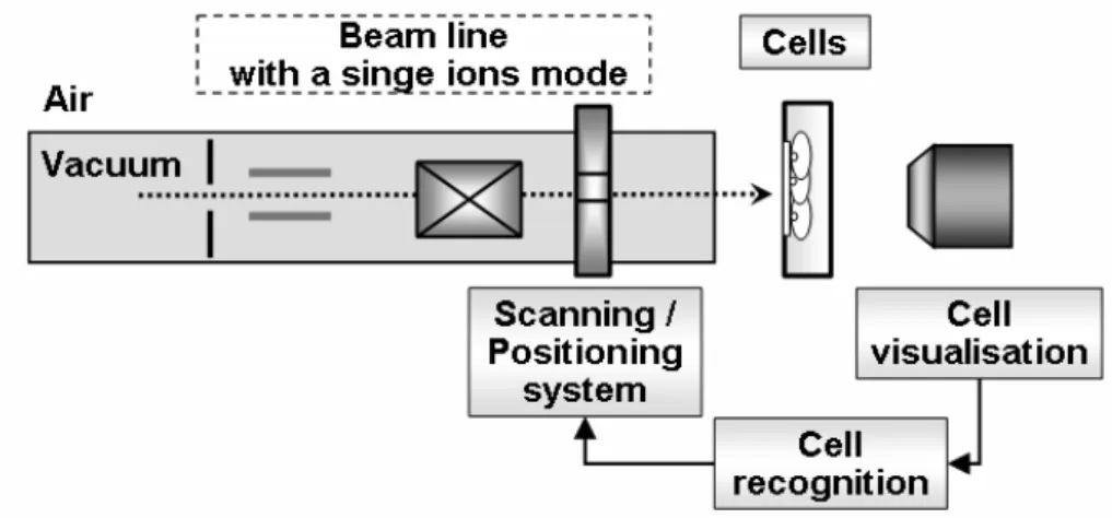
For precise single ion irradiation living cells, some additional elements should be introduced to the basic design of the SIHF (Fig. 1.2).
Fig. 1.2. The schema of the SIHF modifications required for the living cell irradiation
For the irradiation of the living targets, such as biological cells, experiments must occur in the air conditions (not in vacuum). Therefore, external ion beams are used in such experiments. The system of cell visualization (see Section 1.2) and cell recognition (see Section 1.3) are essential to determine the precise target (cell) location. The cell recognition can be performed manually or automatically. Both cell visualization and recognition, closely connected with the positioning system, are responsible for the precision of the ion delivering to the defined cell location.
1.2 Cell visualisation
An important issue of the construction of the SIHF dedicated to cell bombardment is the visualisation of cells during irradiation experiments (a so called on-line cell visualisation). There are two main problems of the on-line cell visualization in SIHF. First, living cells, being almost transparent objects, are invisible in the reflected light. Second, although they can be (hardly) visualised in transmitted light illumination, there have been no constructive solutions for the on-line introduction of illumination source.
Some SIHF groups do not use the on-line cell visualisation and apply pattern irradiation (Reinert T. et al., 2004; Dollinger G. et al., 2005). In most of existing SIHFs, the on-line cell visualisation is made by the staining of cells using fluorescent dyes (Folkard M. et al., 2002; Greif K.D. et al., 2004; Randers-Pehrson G. et al., 2001). However, it is evidently more advisable to study unstained cells and cells unaffected by UV irradiation. In the case of living cells, staining may change the nature of the analyzed cells. Further more, the UV radiation used to observe the fluorescence of stained cells may be highly damaging to the living cells.
The alternative to staining can be i) use of brightfield (darkfield) microscopy, if the problem of illumination is solved; ii) use of the so called phase sensitive techniques, which are able to “see” differences in phase of light passing trough different parts of the object. Some of phase sensitive techniques (Trigg et al., 1995) such as 'Standard Phase Contrast' (e.g. Zernike Phase Contrast), 'Nomarski Differential Interference Contrast' (DIC), 'Hoffman Modulation Contrast' (HMC) or 'Interference-contast', are difficult to implement at the SIHF end-station because of non-standard construction requirements: they must be tailored to work in a horizontal position and, usually, space for placing them at the beam line is rather limited. Therefore, the most appropriate phase sensitive technique of cell imaging without staining seems to be the Quantitative Phase microscopy (QPm).
1.2.1 Brightfield microscopy
The conventional brightfield microscope (Trigg et al., 1995) is most widely used for investigation of samples which partially absorb illuminating light. The technique is best suited for stained specimens, samples naturally absorbing light, or specimens thick enough to absorb a significant amount of light despite being colourless. When illuminating light passes through such specimen, its amplitude or intensity is reduced; therefore, specimen imaged with brightfield illumination is termed an amplitude objects, while the image of such objects is considered to contain so-called intensity (amplitude) information. In a brightfield microscope, illuminating light is aimed through a specimen and through an objective lens to a camera or an eyepiece. We see objects in the light path because the investigated specimen, being an amplitude object, absorbs light differentially. Images produced with brightfield illumination appear dark and/or highly coloured against a bright, often light grey or white, background.
1.2.2 Quantitative Phase microscopy (QPm)
QPm is an image-capturing and analysis tool that has been developed in the IATIA company (Australia, www.iatia.com.au). The method uses an optical microscope utilizing conventional brightfield optics without the need for specialized optical systems to measure transparent samples. Next, a patented digital Quantitative Phase Imaging (QPI) algorithm (Barone-Nugent E.D. et al., 2002; Curl C.L. et al., 2004) provides quantitative phase and intensity data. QPm provides independent digital acquisition of both quantitative phase and amplitude (intensity) information. It should be stressed that no other phase visualization technique delivers the pure phase information only – in other phase sensitive techniques the phase image contains always some intensity information, too.
The QPI algorithm is based on the paraxial approximation of the propagation of intensity distribution as described by the Transport of Intensity Equation (Teague M.R. 1983):
( )
r[
I( )
r( )
r]
Iwhere the light at wavelength λ travels along the z direction, λ π 2 = k , rr =
( )
x,y , is the irradiance,( )
rI r ϕ
( )
rr is the phase and ⎟⎟⎠ ⎞ ⎜⎜ ⎝ ⎛ ∂ ∂ ∂ ∂ = ∇⊥ y x, .
The solution for phase in the Transport of Intensity equation can be presented by the following formula:
⎭ ⎬ ⎫ ⎩ ⎨ ⎧ ⎥⎦ ⎤ ⎢⎣ ⎡ ∇ ∇ ∂ ⋅ ∇ ∇ − = − ⊥ ⊥ ⊥ − ⊥ I I k 2 1 2 z ϕ . (1.2)
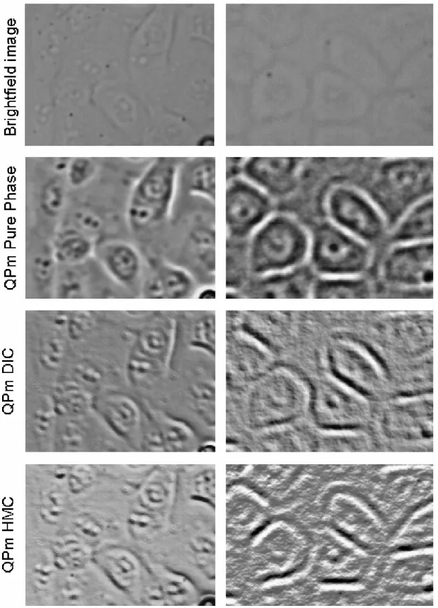
The powerful ability of the QPI algorithm is to regain the phase information from only two ordinary brightfield images which are taken at two planes, slightly different from the focal plane (Fig. 1.3). In addition, a third image, generally used for normalisation, is taken at the focus plane. The phase data is rendered as a grey scale image (the phase map), and represents the phase or optical density across a sample that is entirely free of intensity based data.
Fig. 1.3. Principle of the Quantitative Phase microscopy.
QPm has a number of key advantages, including: a) operating with phase and intensity information independently; b) working in both transmitted and reflected illumination; c) providing quantitative, absolute phase; e) working with non-uniform and partially coherent illumination.
1.3 Cell recognition
The cell recognition can be realized either manually or automatically. In both cases, it is used to localize the place of the targets (cells) where the ions must be delivered. To obtain statistically significant results, many cell irradiation experiments with a large number of cells have to be carried out. Obviously, such task can be realized only using an automatic cell recognition.
The cell recognition is a particular case of pattern recognition. Thus, the cell recognition can be based on such techniques as Neural Networks (Egmont-Petersen M. et al., 2001; Han M. and Xi J., 2004), Fuzzy Logic (Chi Z., 1996; Nachtegael M.D. et al., 2006), direct Image Processing (Gonzalez C. and Woods E., 2001), etc.
Some of SIHF groups use the direct Image Processing for recognition of cell colonies (Barber P.R. et al., 2001). The others use commercial software (mainly Image Pro, Media Cybernetics) also based on the direct Image Processing. The main disadvantage of the commercial software is that it cannot be linked directly with the SIHF controlling software or it cannot include such software in itself. Additionally, the commercial software can be limited by the number of image processing techniques already realized by a company. Thus, while developing the SIHF for cell irradiation, in the present work, the tailored software for the automatic cell recognition has been chosen to be developed.
1.4 Recent experiments of cell irradiation
Development of SIHF and focused microbeam systems for single cell irradiation opens new possibilities for radiobiological researchers. Targeted irradiation is extremely useful in such studies, since it delivers a well-defined number of charged particles directly to cellular and sub-cellular structures. Therefore, the main contribution of SIHF in radiobiology is seen in so-called cellular micro-irradiation investigations (Folkard M. et al., 2001). The main aims of cellular micro-irradiation are to study and understand the following issues:
- mechanisms of radiation action on cells (energy deposition in cell, subsequent damage of cellular and sub-cellular structures, etc.);
- response of cells to irradiation (radiation-induced cellular effects, like death, apoptosis, damage repairing, intracellular and cell-to-cell signalling, mutation induction, etc.).
Such knowledge is crucial in the area of radiomedicine and radiodosimetry to improve the efficiency of radiotherapy strategies and radiation risk estimates.
Examples described below show some mechanisms of radiation interaction with cells and cellular responses to this action studied using the SIHF technique.
1.4.1 Mechanisms of radiation action on cells
The effectiveness of an ionizing radiation (i.e. the number and the quality of the effects induced by radiation) critically depends both on a radiation type (i.e. photon, particle) and on its energy. Therefore, there is a need to introduce a certain classification. Radiation is often classified in terms of its ‘ionization density’. The quantity used to measure ionization density is called Linear Energy Transfer (LET). LET measures the amount of energy lost by a particle or a photon traversing a unit distance. This quantity is often expressed in units of keV/µm.
The ionizing radiation is divided into two types (see Table 1.1): - low LET (sparsely ionizing) – γ-rays, X-rays and neutrons;
- high LET (densely ionizing) – α-particles, protons and heavy ions.
Table 1.1. LET values for different types of ionizing radiation.
Radiation LET (keV/µm)
250kV X-rays γ-rays <1 protons neutrons 1 – 50 α-particles 100 – 200 heavy ions ≥ 1000
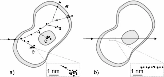
The main reason of such distinguishing is the fact that radiation of different types and LET values produce different patterns of ionization passing through a cell. Fig. 1.4 presents two examples of ionizing patterns induced in a cell by low LET X-ray or γ-X-ray radiation (left image) and high LET α-particle radiation (right image).
In the first case (Fig. 1.4 a), a photon passing trough a cell transfers its energy to electrons via either photoelectron or Compton effects or producing electron-positron pair. In dependence on the occurring effect, these electrons have different energies and, next, transfer energy to subsequent electrons. All secondary electrons produce a pattern in the form of a cascade. In the second case (Fig. 1.4 b), an α-particle induces the ionization in the well-determined volume along its flight path.
Fig. 1.4. Ionization patterns induced in cells by low LET X-ray radiation (a) and high LET α-particle radiation (b).
Both types of ionization patterns lead to subsequent damages of cellular and sub-cellular structures. The most serious consequences for a cell appear in the case of DNA helix damage.
Radiation might induce DNA damage either directly or indirectly. Direct damage results from direct targeting a DNA strand by the irradiating particle. Indirect damage is induced by free radicals originating from the reactions between radiation-induced secondary electrons and intracellular water (see Fig. 1.4 a).
DNA damages are classified into several types in dependence on the number of breaks and the distance between them (see Fig. 1.5).
SSB – single strand break DSB – double strand break
Fig. 1.5. Classification of the DNA strand breaks by complexity (Charlton D.E. and Humm J.L., 1988; Nikjoo H. et al., 1997).
Some additional types of the radiation-induced DNA damage are i) base damage (knocking out basic nitrogens – building blocks of DNA) and ii) formation of anomalous DNA-protein bonds.
1.4.2 Cellular response to irradiation
The described above radiation-induced DNA damage may lead to different consequences for a living cell.
In the case, when radiation doses exceeds the cell possibility for self-repairing two types of cell death may occur: apoptosis or necrosis. Apoptosis (suicidal death) is a natural physiological death of a cell, being a part of the normal growing process. It prevents the subsequent transferring of induced mutations. Oppositely, necrosis is an uncontrolled sudden death of a cell. Both cell death types significantly differ in consequences.
One more type of the cell death may occur as a result of radiation-induced DNA damage – a mitotic death. The mitotic death appears if radiation breaks a DNA strand into several pieces and this damage is not repaired till cell division (mitosis). Then, the cut-off pieces form the structures, called micronuclei. This process leads to the death of cells of the next generation, which has lost a part of the genetic information included in micronuclei.
Certainly, a lot of other biological effects may occur in living cells in response to radiation-induced damages. However, the effects presented above are presently the most studied using targeted irradiation facilities.
It is worth to notice, that most of effects appearing in biological objects in response to radiation are supposed to follow the so-called ‘linear no-threshold model’ (Fig. 1.6; Trott K.R. and Rosemann M., 2000). According to this model, the probability of the given effect (radiation risk) is directly proportional to the radiation dose.
Fig. 1.6. ‘Linear no-threshold model’ of radiation risk.
The model was mainly developed from the data obtained studding the large groups of people who received doses much higher than background (survivors of atomic bomb explosions, power plant disasters, uranium miners, etc.).
Effects induced by doses in the range of usual background (low-dose effects) are not known at the same extent. During the last century, they were usually extrapolated from higher doses data using the ‘linear no-threshold model’. However, some serious apprehensions for applicability of this model to low-dose effects appear. This was caused by recent discovery of several low-dose and non-targeted effects where cells are found to give an indirect response to ionizing radiation. These are:
a) adaptive response – cells subjected to a low priming dose show a lesser response when subsequently challenged with a higher dose (Wolff S., 1998);
b) low-dose hypersensitivity – cells exhibit increased radiation sensitivity at low doses (Joiner M.C. et al., 2001);
c) inverse dose–rate effect – cells manifest the increased levels of mutations or transformations at very low dose rates (Vilenchik M.M. and Knudson A.G., 2000);
d) bystander effect – the unirradiated cells die in response to the signalling processes arising from irradiated cells (Prise K.M. et al., 2003);
e) gene expression – which is the up, or down regulation of genes at doses below levels significant for direct DNA damage (Amundson S.A. et al., 1999);
f) genomic instability – cell lines manifest chromosome changes and mutations in the surviving progeny of irradiated cells (Wright E.G., 1999).
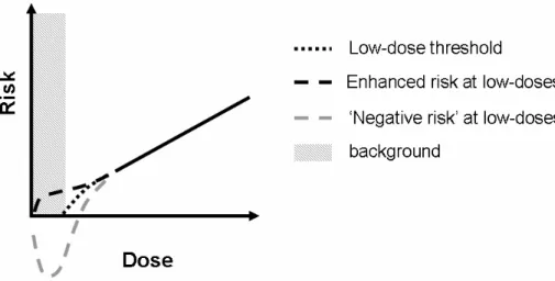
Although the investigations of these effects are far from complete, by analyzing them one can conclude that the ‘linear no-threshold model’ requires modifications in the low-dose range. And there is still a question which of possible models (see Fig. 1.7) will properly describe the low-dose effects.
Fig. 1.7. Several possible models of the radiation risk for low-dose range.
Such uncertainty shows the necessity for careful studies of the effects described above, in order to construct the model for the low-dose radiation risk. Taking into account the capabilities of SIHF, this technique gives a great opportunity for such studies, which is confirmed by the increasing number of recently reported scientific papers about SIHF applications in low-dose effects’ investigations.
1.4.3 Recent radiobiological investigations using SIHF
Last years have brought a number of papers reporting the cell irradiation experiments with defined number of charged particle (Zhou H. et al., 2000; Prise K.M. et al., 1998; Belyakov O.V. et al., 1999; Folkard M. et al., 2001; Sawant S.G. et al., 2002; Prise K.M. et al., 2000; Kobayashi Y. et al., 2003) or with X-ray radiation (Prise K.M. et al., 1998; Belyakov O.V. et al., 1999l; Schettino G. et al. 2005). The studied radiation induced effects such as bystander effect (Prise K.M. et al., 1998; Zhou H. et al., 2000; Sawant S.G. et al., 2002), micro nucleus formation (Belyakov O.V. et al., 1999; Prise et al. 2000), cell lethality (Belyakov O.V. et al., 1999; Kobayashi Y. et al., 2003) has been performed for different cell lines, e.g. human fibroblasts (Prise K.M. et al., 1998; Belyakov O.V. et al., 1999) and chinese hamster cells Prise K.M. et al., 2000; Sawant S.G. et al., 2002; Kobayashi Y. et al., 2003).
The above mentioned studies employ different types of ionizing radiation (α-particles, heavy ions, and X-rays) with a broad range of LET values. After the analysis of these works, one may conclude that among the most studied cellular effects induced with application of SIHF there are: micronuclei formation, cell lethality and bystander effect.
In the present work, the micronucleus formation and cell lethality effects were chosen as the principal effects to be studied using the developed SIHF. In addition, the study of radiation-induced double strand breaks of DNA of irradiated cells was carried out as well.
Most of SIHF groups use α-particles, heavy ions or X-ray setups. Taking into account the importance to provide the experiments with different types of ionization, the Cracow SIHF would extend the present knowledge about radiation-induced biological effects providing the possibility to study the effects induced by protons in living cells.
CHAPTER 2. DEVELOPING THE SIHF HARDWARE 2.1 Introduction
In the literature review, it has been shown an expediency of SIHF development on a base of working microbeam systems. Such approach has been applied in the present work: the presented SIHF has been developed on a base of fully operational microbeam setup. For this aim, the Cracow microbeam (CMB) has been used.
The present chapter gives a brief description of the CMB and explain the main modifications that have to be performed in order to construct a SIHF on the base of it. The main hardware modifications are explained in the present chapter, while the software specially developed for the SIHF is described in Chapter 3.
2.1.1 Cracow microbeam (CMB)
−
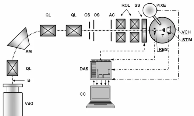
a base for SIHF developmentThe nuclear microbeam in Cracow (Fig.2.1) is based on a HVEC KN-3000 Van de Graaff accelerator (A) with a proton (alpha particle) beam energy ≤ 3 MeV and an energy stability of ∆E/E ≈ 10-3. Brief depiction of the CMB is presented in Fig.2.1. while the detailed information about the system construction can be found elsewhere (Lebed S. et al., 2001; Lekki J. et al., 2001).
The CMB currently provides a minimum beam spot size of about 7-8 microns at beam current of 100 pA (for beam current of 0.5 – 1 nA, which is more suitable for PIXE measurements, the beam spot size is of 10 microns). The scanning system provides the scanning area up to 0.25 x 0.25 mm (can be extended twice, if required). The CMB enables measurements using such micro analytical techniques (Cambell J.L., 1993; Maydell E.A., 1993) as Proton Induced X-ray Emission (PIXE), Rutherford Back Scattering (RBS), and Scanning Transmitted Ion Microscopy (STIM).
Fig. 2.2. Scheme of the Cracow MB. The ion beam (B) from the accelerator (VdG) is delivered to the circular slit (CS) via a 900 double-focusing analyzing magnet (AM) and three doublets of magnetic quadrupole lenses (QL). Only central part of the beam can pass through the circular slit to the object slit (OS). Passing an angular collimator (AC), the beam is next focused by means of two doublets of magnetic quadrupoles, forming the so-called divided Russian quadruplet lenses (RQL). The beam is focused on a target (T) inside the vacuum chamber (VCH). The detectors placed inside the chamber enable the PIXE, STIM and RBS measurements. A ferrite-cored scanning system (SS) is used to carry out the micro-analytical measurements in two dimensions. The detectors and the scanning system are connected to a controlling computer (CC) via data acquisition system (DAS) based on PC data acquisition cards and CAMAC.
2.1.2 From CMB to SIHF
The CMB facility is a fully operational system for micro analytical analysis. In the present work, however, it is used only as a base for the SIHF development. The main point is that the CMB provides the solution of well focused microbeam formation in vacuum. Whereas, for single ion irradiation of living cells it is required to introduce additional solutions. Fortunately, the CMB is an open system to which a new hardware (detectors, CAMAC units, new end-station, etc.) can be easily added.
For irradiation of the living targets (cells), the ion beam should be led out from the vacuum and focused in air. For this purpose, a special chamber had to be designed, since the end-station of the CMB includes a vacuum chamber designed in such a way that the focus point of the ion beam is inside it.
For the precise ion number control, two requirements has to be realised: i) the beam current should be decreased to about 1000 protons/s and ii) the possibility should be provided to switch off the beam after detection of every single ion (the so-called beam blanking). To provide the accurate beam blanking, the effective ion detection should be carried out. It can be realised via introducing the particle detector either inside, or outside the chamber.
The scanning system of the CMB could be used for delivering the ions to the defined target point. However, it covers too small region of interest (0.25 x 0.25 mm area). Therefore, it is reasonable to introduce a special system for positioning the targets (cells) in the SIHF. Another important requirement is the construction of special holders for living cells, which would be suitable for both culturing and irradiation of cells.
In order to observe and localise living cells for their subsequent irradiation, an optical system should be introduced at the end-station of the SIHF. The task of cell visualisation is complicated, since living cells are usually semi-transparent or even transparent objects almost not visible in the conventional optical system.
Taking into account the hardware modifications, certain data acquisition modifications should be performed as well.
All above-mentioned requirements for the SIHF development are summarized in Fig. 2.3, which presents the schematic illustration of the SIHF.
In general, for single ion irradiation of living cells it is required to solve the following issues:
- beam focusing in air;
- precise ion detection and ion number control, down to one ion; - cell positioning and cell visualization;
- automatisation of cell recognition, cell positioning, and cell irradiation processes.
Fig. 2.3. Schematic illustration of the SIHF. The proton beam (B) enters the SIHF beam line via circular slit (CS). Precise slits (PS) further reduce the beam current. Two electrostatic deflecting plates (DP), mounted after the slits and supported by the angular collimator (AC), allow rapid beam blanking (BB). The beam is focused with two doublets of magnetic quadrupol lenses (RQL). After passing the outlet window (OW) of the chamber (CH), the beam is focused on a Petri-dish (with living cells) mounted on the 3D moving stage (MS). The SIHF end-station includes the detector, either a channeltron detector (CHD) inside the chamber, or a particle silicon surface barrier detector (SiD) placed after the Petri-dish. Cell visualisation system consists of the microscope objective (MO) and the illumination source (diode, D).
The implementation of the first three issues, dealing mainly with the hardware modifications, is described below. It involves both the development of a new end-station, and modifications of the beam line and data acquisition system.
For automatisation of cell recognition, cell positioning and cell irradiation, a special software has to be developed. It is entirely described in the next chapter (see Chapter 3 “Developing SIHF Software”).
2.2 The beam line modifications
The beam line modifications have been aimed for better beam control. First of all, they have included the replacement of the object slit (Fig. 2.2, item OS) with the high precision beam slits (Fig. 2.3, item PS) (construction Technisches Büro S.Fisher,
Ober-Ramstadt, Germany). These slits have allowed the adjustment of the beam size from 50 µm downwards and thus reduction of the beam current to the required flux of about 1000 protons/s (0.16 fA). In that way, the time between two protons hitting the target one after another has been extended (to about 1 ms in average) in order to separate those protons in time for the more effective electronic reduction and computer control.
The precision slits may be also fully opened and therefore their placement in the ion guide is not harmful for the normal microprobe operation (i.e. for the beam intensity of 100 pA and more, not for the single protons regime).
The deflection plates (Technisches Büro S.Fisher) have been located next to the beam reduction slits. Their function is to turn off the beam, when required. Deflection plates are electrostatically driven by a fast high voltage amplifier (HV-amplifier, Technisches Büro S.Fisher), which allows rising the deflection voltage up to 1000 V/µs. The voltage value, sufficient to deflect the beam of protons towards the ion guide and therefore to stop it completely, has been estimated as follows.
Fig. 2.4. Proton moving in electrostatic field of the deflection plates with an initial velocity υv0
perpendicular to the vector of electric field intensityEv.
The proton moving in the electromagnetic field with the velocity υr is affected by the Lorentz force
( )
m pE p( B) dt d p r r r r = + υ× υ (2.1)where mp is the proton mass, p – proton charge, Ev is electric field intensity, and Bv –
magnetic induction. The protons moving between the deflection plates are considered as the charged particles moving in the electrostatic field (Bv = 0). Thus, for the proton
moving in such field with an initial velocity υ0 (t = 0) perpendicular to the vector of
intensity Ev (Fig. 2.4), Eq. 3.1 is equivalent to the equations
0 2 2 = dt x d mp , pE dt y d mp 22 = . (2.2)
Taking into account the initial parameters, the solutions of the Eqs. 2.2 are
( )
υ0 υx t = ,( )
Et m p t p y = υ , x( )
t =υ0t,( )
2 2m Et p t y p = . (2.3)The proton moves along the parabolic trajectory until the end of the deflection plates. The transversal proton velocity component υy′ and the proton deflection h′
from the initial direction of its movement in the moment when the proton reaches the end of the deflection plates, can be estimated using Eqs. 2.3
0 υ υ E l m p p y = ′ 2 0 2 2 υ l E m p h p = ′ (2.3)
The further movement of the proton is described as a uniform motion with a constant initial velocityυvxy =υv0 +υvy′. Thus the total proton deflection h, from the
initial direction of its movement in the moment when the proton reaches the angular collimator, is ⎟ ⎠ ⎞ ⎜ ⎝ ⎛ + = ′ + ′ = E l l L m p L h h p y 2 2 0 0 υ υ υ (2.4)
Taking the velocity υ0 of the 2 MeV protons of about 1.96 · 107 m/s, the plates length l of 0.1 m, the distance L between the plates and the angular collimator of 0.5 m, the distance D between two deflection plates of 0.002 m, the deflection h has been estimated for the values of the voltage U=E·D applied to the deflection plates. Finally, the voltage value of 440 Volts has been applied to the plates. It has resulted in a proton beam deflection h of 3.06 mm, which is sufficient to omit the aperture of the angular collimator (the aperture size d is of 100 µm).
2.3 The end-station
The new end-station for the SIHF has been developed (Fig. 2.5). It is based on the special designed target chamber (Лебедь С.О. et al., 2000).
It includes the outlet window enabling leading the ions out off vacuum, the moving stage, the particle detector and the microscope objective of the on-line optical system (described in Section 2.4).
Fig. 2.5.The end-station of the SIHF.
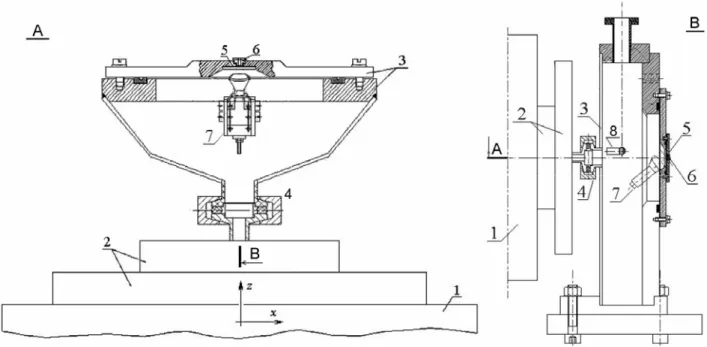
Chamber. Fig. 2.6 presents the design of the irradiation chamber. In the SIHF, the focus of the beam has to be located in air, outside the chamber. The focusing distance of the CMB is 15 cm. Therefore, during the construction of the new irradiation
chamber for the SIHF, the existing limitation of the depth of the chamber has been taken into account.
Fig. 2.6. The schematic view of the irradiation chamber of the SIHF end-station (A – top view, B – side view): 1 – part of the divided Russian quadruplet; 2 – scanning system; 3 – target chamber; 4 – connection of the chamber with the ion guide; 5 – outlet window; 6 – target holder as a part of the positioning system; 7 – secondary electrons detector (channeltron); 8 – illuminating diode. Figure were taken from (Лебедь С.О. et al., 2000)
The chamber includes both the outlet window (see below) and the quartz window. The latter one is used for preliminary beam spot visualization under the conditions of a high current beam (see Section 3.4.2). The details of the chamber construction can be found elsewhere (Лебедь С.О. et al., 2000).
Outlet window. The outlet window used for leading the ions out of the vacuum have been purchased from Silson, UK. The window is a thin (100-200 nm) Si3N4 membrane in the frame made of Si (Fig. 2.7). Different sizes and thicknesses of both the windows and the membranes are commercially available.
Fig. 2.7. The Si3N4 windows. Two differently sized windows are shown: (a) 3 x 3 mm (7 x 7 mm with Si frame) and (b) 1.5 x 1.5 mm (5 x 5 mm with Si frame).
As the outlet window in the SIHF, the 5 x 5 mm windows with the 200 nm thick, 1.5 x 1.5 mm membranes have been used. The membrane of 200 nm thickness has assured tolerable beam scattering and satisfactory mechanical endurance, withstanding the atmospheric pressure.
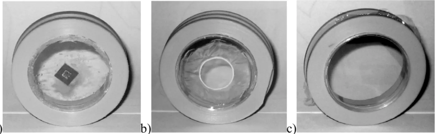
Petri dishes: Three different modifications of the standard Petri dishes (made off polystyrene, 3.5 cm in diameter) have been used for the cell irradiation experiments. For two of them (Fig. 2.8 a and b), a small hole (1 cm in diameter) has been drilled in the centre of the dish and either Si3N4 window (500 nm thick, either 1.5 x 1.5 mm, or 3 x 3 mm sized) or Mylar foil (2.5 µm thick) has been glued by wax or by epoxy adhesive glue specially formulated for medical applications (EP30MED, Master Bond Inc.), correspondingly.
a) b) c)
Fig. 2.8. Three modifications of the Petri dishes: (a) window based on the Si3N4 window and (b) Mylar foil glued over the hole in the dish bottom, (c) Mylar foil stretched on the place of removed dish bottom.
For the third modification (Fig. 2.8 c), a whole bottom of the Petri dish has been removed and it has been replaced with the Mylar foil (2.5 µm thick) in such a way that the foil has been stretched using plastic rings. During irradiation experiments, all types of cell dishes have been covered with a Mylar foil to prevent contamination of cell culture.
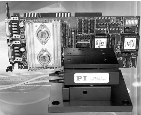
Moving stage. A precise two dimensional V-106 voice-coil moving stage (Physics Instruments, Fig. 2.9) mounted in a vertical position has been used as a base of the positioning system. As the beam line is horizontal, Petri dish with the cells must be placed (and irradiated) vertically. The stage motion in the third direction has been provided via introduction of the extra micrometer screw.
Fig. 2.9. V-106 Voice-Coil Scanning System (in the foreground) and V-820.20 Voice-Coil Scanning Controller (in the background). The picture was taken from www.physikinstrumente.com.
The V-106 voice-coil scanning and positioning system is designed for applications where small samples have to be positioned or scanned with high velocity and high resolution. It provides superior responsiveness compared to micropositioners with conventional leadscrew drives. The mechanics is driven by an integrated, non-contact, zero-friction, voice-coil actuator. Scan velocities up to 50 mm/sec over a range of 5 mm are feasible with typical loads of less than 100 grams.
Integrated linear encoders provide position resolution of 0.1 µm and repeatability of about 0.2 µm.
Ion detection. The first attempt of ion detection has been provided using a couple of Si3N4 window covered with CsI as a source of the secondary electrons and a channeltron (Sjuts Electronics, Fig. 2.10 a) installed in the chamber (Fig. 2.6 item 7).
a) b)
Fig. 2.10. a) Sjuts Electronics channeltron detector (www.sjuts.com) and b) ORTEC silicon surface barrier detector.
However, this way of the ion detection appeared to be not enough reliable – the measured effectiveness was not better than 61 % (Polak W. et al., 2004). Therefore, another way of ion detection has been developed using a particle silicon surface barrier detector (ORTEC, Fig. 2.10 b). This detector has been installed outside the chamber, behind the Petri dish with cells (Fig. 2.3 item SiD, Fig. 2.5). It has provided the proton detection with effectiveness about 100 % (Polak W. et al., 2004).
2.4 Optical system for cell visualization
Observation and evaluation of cell samples must be assured before, during and after the irradiation. Moreover, to make the subsequent automatic cell recognition more efficient, the high quality of cell images must be provided. Two main solutions have been developed at IFJ PAN for cell visualization purposes. These are brightfield (conventional) cell visualisation and cell visualisation based on Quantitative Phase microscopy (QPm). It has been shown, that both techniques can be used either for off-line cell inspecting (in preparatory room before and after irradiation) or for on-line cell observation (during cell irradiation).
2.4.1 Brightfield (conventional) cell visualisation
Generally, the brightfield microscopy is applied to visualize samples that absorb a significant amount of visible light (see Section 1.2). The main equipment required for brightfield cell visualisation is a light source for sample illumination, a lens (objective) for image magnification and a camera for image registration. These basic elements are present in both off-line and on-line visualisation systems, which have been proposed for the SIHF.
Off-line cell visualisation system. The proposed brightfield off-line cell visualisation system is based on research Olympus BX-51 research microscope (Fig. 2.11 a). The Olympus BX-51 allows using not only a high quality light source (built-in Koehler illumination for transmitted light 12V 100W halogen bulb) and a wide range of objectives (4x, 10x, 20x, 50x), but also other microscope modules (condenser, filters etc.) serving to enhance the quality of the obtained image.
a) b)
Fig. 2.11. Olympus BX-51 microscope (a) and QICAM 12-bit digital camera (b).
For image registration, a QICAM 12-bit digital camera has been used (Fig. 2.11 b). This camera provides 1392 x 1040 pixel (1.4 million) image with 1/2″ optical format.
On-line cell visualisation system. A separate brightfield on-line cell visualisation system has been developed. It consists of Philips Lumiled LUXEON emitter (www.lumileds.com) as a light source, Thales Optics Zoom 125C (www.qioptiqimaging.com) as an advanced objective and KOBI B/W CCTV Camera (www.dipol.com.pl, www.kobicctv.com) for image registration.
In our SIHF, the realization of brightfield on-line cell visualisation has become possible mainly due to the proposed method of sample illumination. The illuminating emitter has been installed directly inside the chamber of the SIHF and thus the ion exit window serves as an illumination source. The chosen Philips Lumiled LUXEON emitter (Fig. 2.12 a) is characterized by the brightness of 45 lumens, the power consumption of 1 Watt, and the lifetime of 50000 hours. Its representative spatial radiation pattern is presented in Fig. 2.12 b. The emitter size is 9.6 x 9.6 x 5.8 mm. The light beam of the emitter contains no infrared or ultra violet components.
a) b)
Angular Displacement (Degrees)
Fig. 2.12. Philips Lumiled LUXEON emitter (a) and representative spatial radiation pattern for the emitter (b) (www.lumileds.com).
The used Zoom 125C setup (Fig. 2.13 a) delivers a magnification in the range of 1x – 12.5x zoom ratios. The Zoom 125C is characterized by a 89 mm working distance and a field of view ranging from 3.4 x 4.5 mm2 to 0.27 x 0.37 mm2. Its performance is enhanced with a remote motorized zoom and internal 5 mm and 15 mm fine focuses controls.
a) b)
Fig. 2.13. Thales Optics Zoom 125C (a) and KOBI B/W CCTV Camera (b).
The images have been registered using KOBI B/W CCTV Camera (SG32M-1CE AI/DC, Fig. 2.13 b) attached to the Zoom 125C. The camera is characterized by the high sensitivity of 0.005 lx (important in low illumination conditions), signal to noise ratio of 48 dB, 1/3″ optical format, and resolution of 537 x 505 pixels.
2.4.2 QPm visualisation
The advantage of the Quantitative Phase microscopy is its ability to obtain only the phase information about imaged object, enabling thus the observation of the transparent and semi-transparent samples, even those not visible for conventional visualization methods (see Section 1.2).
For both off-line and on-line optical systems proposed in the work, the QPm construction requires the only mechanical detail – a P-721 PIFOC® High-Speed Piezo Nano-Focussing Device with direct metrology feedback (Physics Instruments, Fig. 2.14). This device allows fast moving of the objective from the focal plane to two planes located on the both sides from the focal plane. The images are taken in each of these three planes.
Fig. 2.14. P-721 PIFOC® High-Speed Piezo Nano-Focusing Device (www.physikinstrumente.com).
P-721 PIFOC® provides a positioning and scanning range of 100 µm with sub-nanometer resolution (± 0.7 nm) and a very high linearity (0.03 %). The distance between the focal plane and the plane out of the focus is in a range of 0.5 – 20 µm and depends on a magnification of used objective (see Table 2.1).
Table 2.1. Dependence of the defocusing distance on the objective magnification.
Objective magnification 2.5x 10x 20x 40x 100x
Defocusing distance 20.0 µm 5.0 µm 2.0 µm 1.0 µm 0.5 µm
Off-line system. Just like the brightfield off-line system, the QPm off-line cell visualisation has been based on the research Olympus BX-51 microscope (Fig. 2.11 a). In the QPm system, additionally, the P-721 PIFOC® device has been mounted between the microscope objective and revolver. For image registration, the QICAM 12-bit digital camera described above (Fig. 2.11 b) has been used.
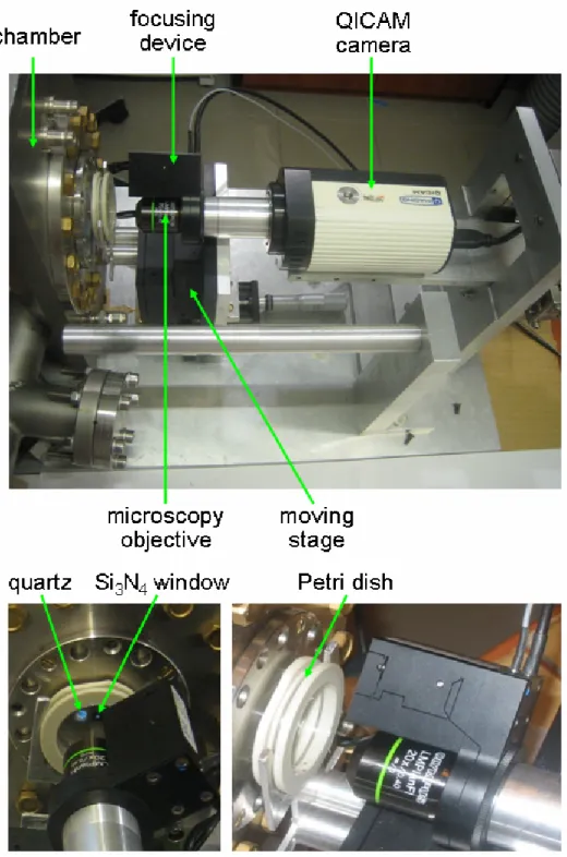
On-line system. The QPm on-line visualisation has been developed using the P-721 PIFOC® device, Olympus objectives (4x, 10x, 20x, 50x), and the QICAM digital camera (Fig. 2.15). All elements of the system have been directly mounted as the part of the end-station as shown in Fig. 2.15.
Fig. 2.15. QPm based on-line visualisation system.
2.5 Data acquisition modifications
The aim of data acquisition system (DAS) is to provide an interface between electronic parts of the SIHF and a computer. The data acquisition system of the CMB (Lekki J. et. al., 2000) has been used as base of the DAS for the SIHF. However, the added electronic modules have caused certain data acquisition modifications.
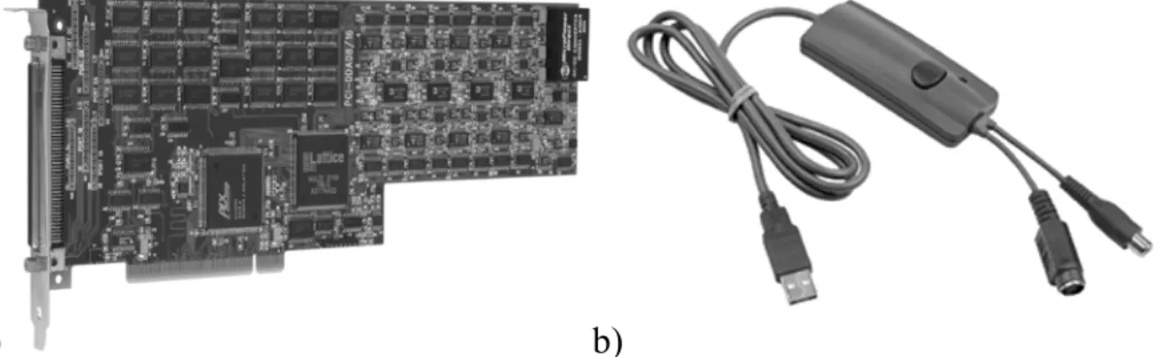
First of all, the beam blanking has required the addition of PCI-DDA 08/16 analog output and digital I/O board (Measurement Computing Company). The PCI-DDA 08/16 (Fig. 2.16 a) provides eight analog output channels, which are characterized by 16 bit resolution, ±0.63 mV accuracy, 12 µs settling time and 2.5 V/µs slew rate. The board receives signal related to the ion passage and generates the signal to switch off the beam.
a) b)
Fig. 2.16. a) PCI-DDA 08/16 computer board; b) GA-VD201G High Quality Video Creator (www.cooldrives.com).
Secondly, the V-820.20 Voice-Coil Scanning Controller (see Fig. 2.9) has been added for direct stage control. This digital controller comes on an ISA-bus-card for industrial PCs and features the on-board linear amplifiers for two individual axes, a 32-bit PID-V-ff servo system, as well as I/O lines and hardware interrupt capability.
Thirdly, the GA-VD201G High Quality Video Creator (Fig. 2.16 b) has been added to digitize the video signal from KOBI B/W CCTV Camera. It supports NTSC, PAL video inputs and high resolution still image capture at 720 x 576 pixels.
2.6 Results and discussion
Beam line. Influence of the equipment newly introduced in the beam line, such as the precise slits and the deflection plates, has been checked in the following way. First, under the conditions of the slits being open and zero voltage on the deflection plates, the beam flux of about 10000 protons/s was set. Next, the flux was measured while operating with the precise slits. The slits allowed, for smooth control, reducing the beam down to the chosen optimal current value of about 1000 protons/s. Then,
the voltage of 440 V was applied to the deflection plates. It reduced the measured current to zero value, which indicated the successful beam deflection (beam blanking). After the setting, the system has been put back to the initial conditions with open slits and zero voltage on the deflection plates, and the previous beam flux was restored.
End-station. The next important part of the SIHF is the end-station. Its main task is getting the beam out of vacuum. To verify the beam behaviour in air, the following test has been carried out. The ion beam has been guided through the outlet window outside the chamber. Directly behind the window, a copper grid has been mounted on the holders designed for the Petri dishes. Using the CMB scanning system and the externally mounted particle silicon surface barrier detector, the scanned image of the grid has been obtained Fig. 2.17. The image has been constructed as the map of number of counts corresponding to the energy value of the beam coming through the grid in each pixel of the scanned area. On the map, the lighter colour corresponds to the higher number of counts.
Fig. 2.17. Copper Kα image (128 x 128 pixels) of the Cu grid (mesh size 63 µm, Cu bar diameter 9 µm). Estimated beam spot size was of about 15 µm (FWHM).
The first detecting system based on the channeltron has shown the efficiency of 60 % (Polak W. et al., 2004). It is definitely not enough for SIHF that requires efficiency up to 100% and thus control of every single ion. Efficient ion detection is